Testing Oops! All Servos!
This article includes sponsorship or links with referral codes which will earn me an affiliate fee. These are clearly marked with a 💵 symbol.
As mentioned in my last Oops! All Servos! post, I had three things left to test on my boards for me to be happy with them and their performance.
The first was the bidirectionality of the level-shifters, the second was confirming the current measurement header worked as expected and the third was a test of the limits of the board.
For transparency, the development of Oops! All Servos! has been sponsored by JLCPCB💵 and for anyone who's not followed along with this series the Oops! All Servos! is an expansion board for Seeed Studio XIAO and Adafruit QT Py microcontrollers, with JR-style servo headers on all 11 GPIO pins. Each pin also has a bidirectional 3.3 v to 5 v level shifter, and the board has external power input including a current measurement point.
Bidirectional level-shifters
My first check to ensure truly bidirectional level-shifters is a loop-back test. I hooked up a jumper between the Servo 0 and Servo 6 pins, since both of those pins' 3.3 v and 5 v traces are broken out to test points.
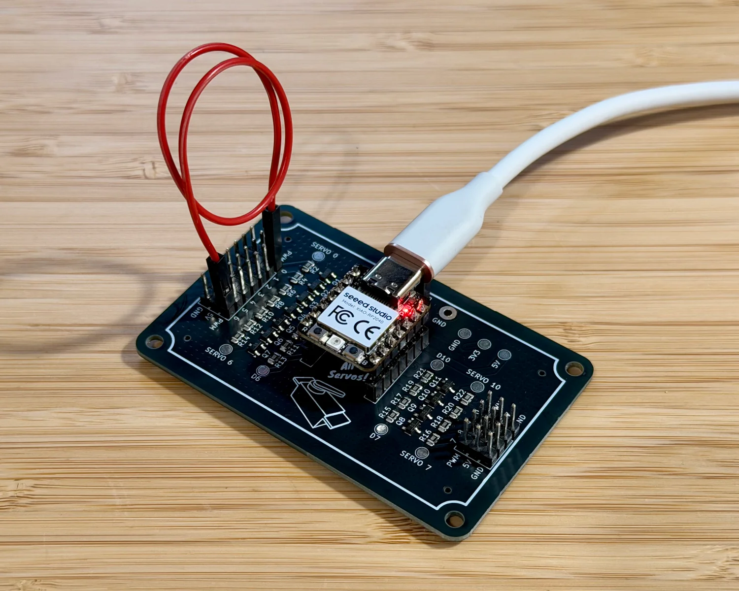
With a small amount of CircuitPython code, I could then toggle D0 on and off and observe the input value on D6.
import board
from time import sleep
from digitalio import DigitalInOut, Direction, Pull

out_pin = DigitalInOut(board.D0)
out_pin.direction = Direction.OUTPUT

in_pin = DigitalInOut(board.D6)
in_pin.direction = Direction.INPUT
in_pin.pull = Pull.UP

while True:
    out_pin.value = False if out_pin.value else True
    print(str(in_pin.value))
    sleep(0.5)
Probing the 5 v side of D0 and the 3.3 v side of D6 with my oscilloscope shows the signal toggling on and off, in line with the code.
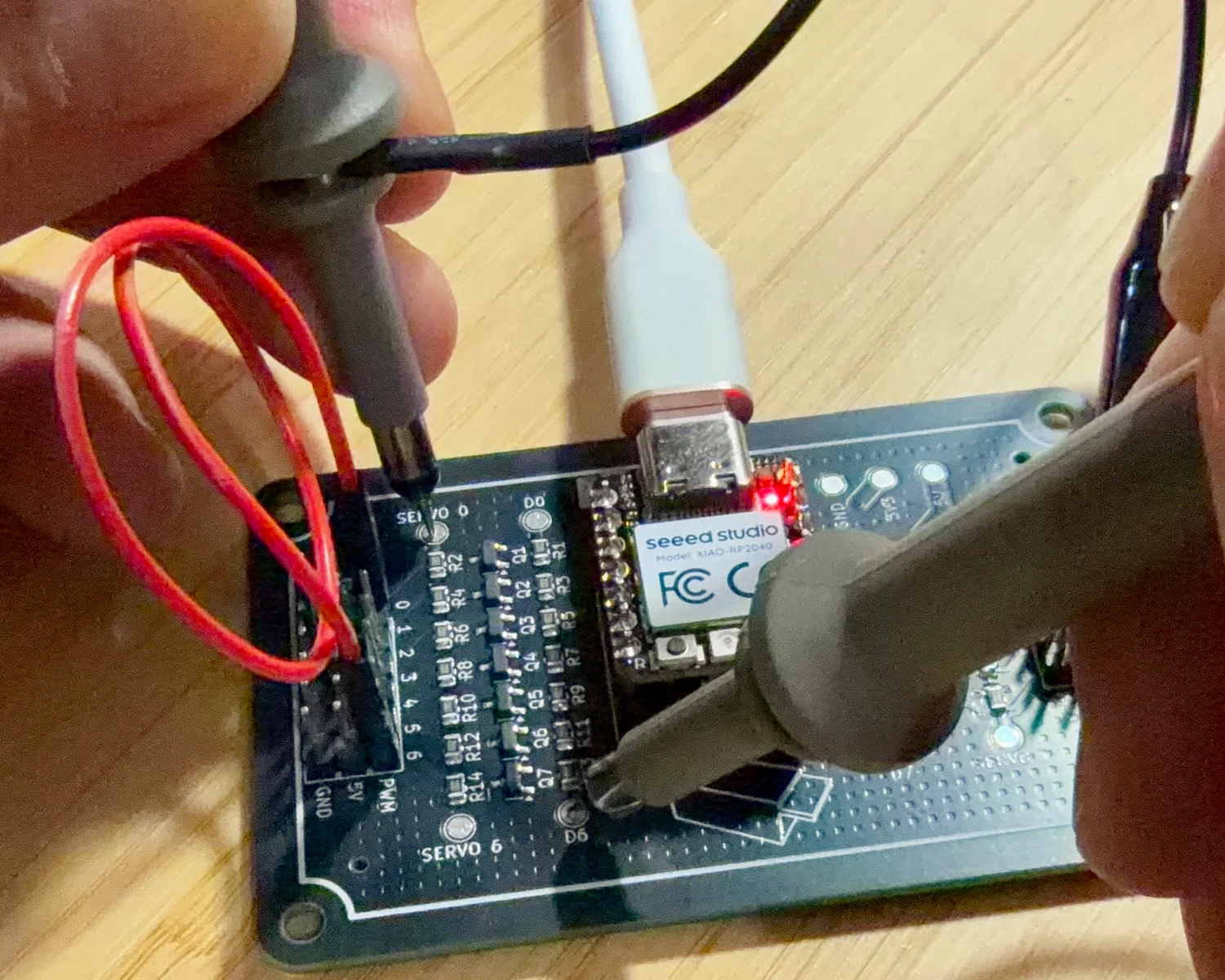
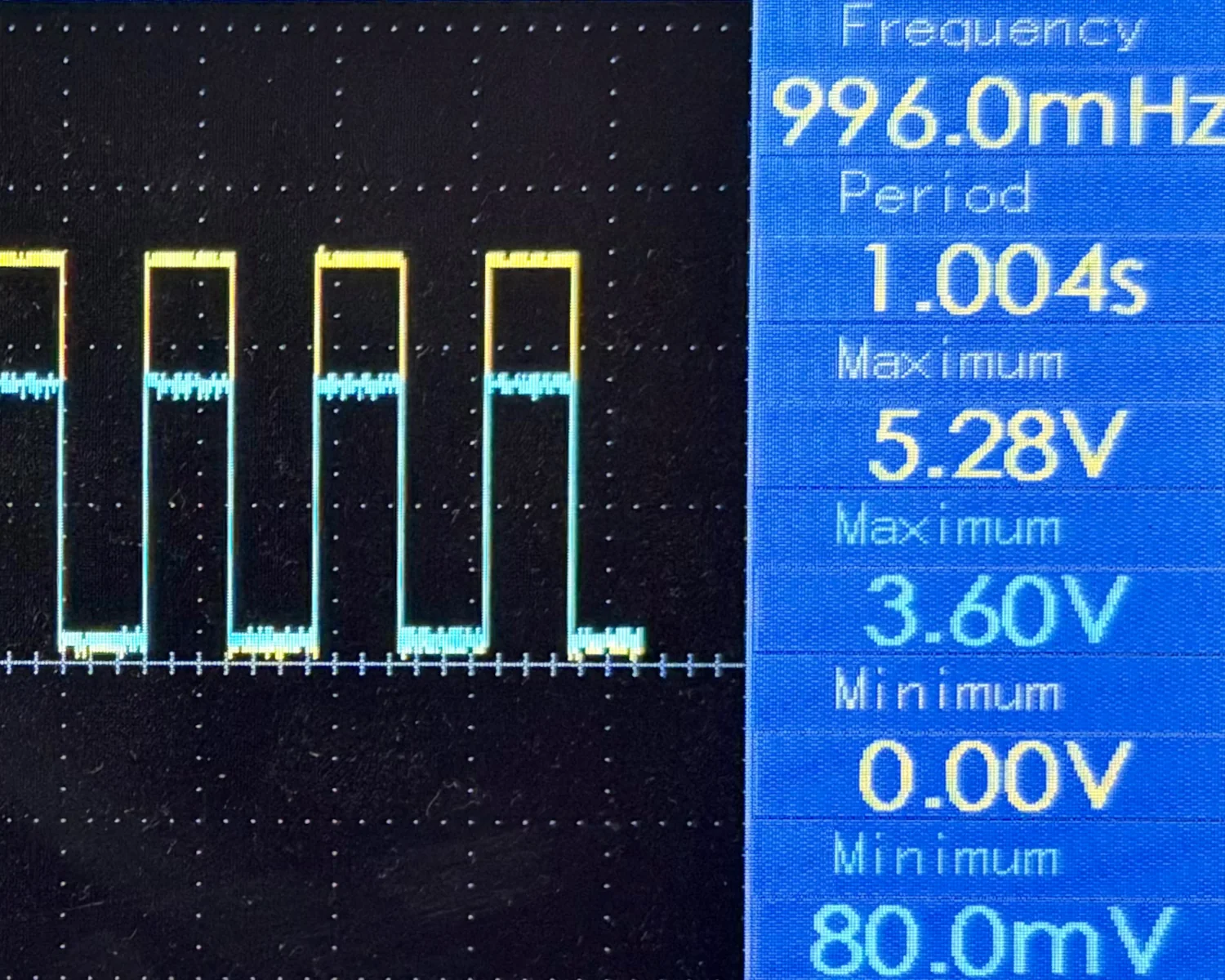
We can see that the 5 v signal is being translated down to 3.3 v as expected. What a relief!
For the next test I wanted to check whether one board could talk to another, using all 11 pins. This time, I wired two boards together, Servo 0 to Servo 0, Servo 10 to Servo 10, etc.
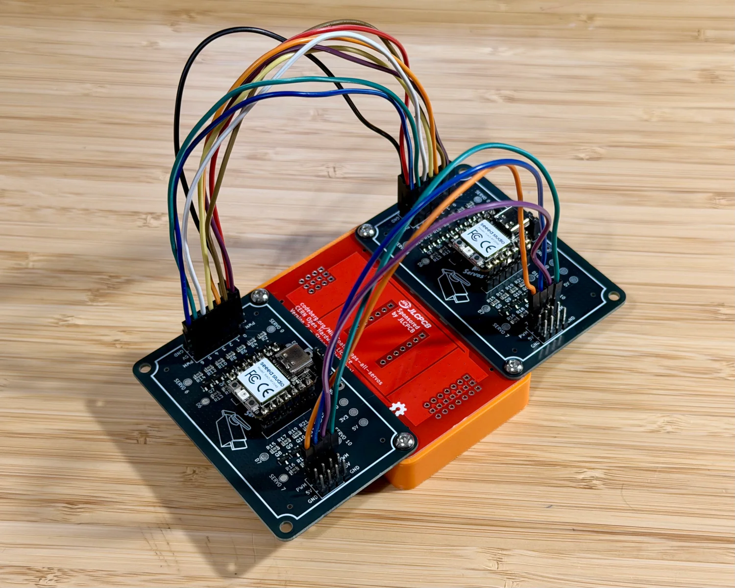
I wrote some more CircuitPython code to cycle through all possible states of 11 pins.
The easiest way to achieve this is to count from 0b00000000000 to 0b11111111111, which is 211-1, or 2047.
We can then take the bit from each position and toggle that GPIO pin to match.
from board import D0, D1, D2, D3, D4, D5, D6, D7, D8, D9, D10
from time import sleep
from digitalio import DigitalInOut, Direction

pins = [
    D0, D1, D2, D3, D4, D5, D6, D7, D8, D9, D10
]

output = [DigitalInOut(pin) for pin in pins]
for pin in output:
    pin.direction = Direction.OUTPUT

while True:
    for step in range(0,2048):
        binary = f'{step:011b}'
        bits = [c == '1' for c in binary]
        for pos in range(0,11):
            output[pos].value = bits[pos]
        print(f'{step:04} = {binary}')
        sleep(0.1)
On the receiving end, we can then run the same process in reverse. Read in the values of all 11 GPIO pins, convert them to a number and print that out. One nice trick in regard to timing is to only act whenever the LSB changes. This way the second microcontroller will keep its reads in sync with the first as the LSB changes with each step in the loop.
from board import D0, D1, D2, D3, D4, D5, D6, D7, D8, D9, D10
from time import sleep
from digitalio import DigitalInOut, Direction, Pull

pins = [
    D0, D1, D2, D3, D4, D5, D6, D7, D8, D9, D10
]

input = [DigitalInOut(pin) for pin in pins]
for pin in input:
    pin.direction = Direction.INPUT
    pin.pull = Pull.UP

prev_lsb = input[10].value
while True:
    lsb = input[10].value
    if lsb != prev_lsb:
        bools = [pin.value for pin in input]
        bits = ['1' if bit else '0' for bit in bools]
        binary = ''.join(bits)
        step = int(binary,2)
        prev_lsb = lsb
        print(f'{binary} = {step}')
    sleep(0.01)
On the first microcontroller's console, we see the current step and the calculated binary presented to the GPIO pins.
...
128 = 00010000000
129 = 00010000001
130 = 00010000010
131 = 00010000011
132 = 00010000100
133 = 00010000101
134 = 00010000110
...
On the second, receiving, end we see the binary as read from the GPIOs and the calculated decimal value.
...
00010000000 = 128
00010000001 = 129
00010000010 = 130
00010000011 = 131
00010000100 = 132
00010000101 = 133
00010000110 = 134
...
As long as we see this calculated value incrementing by 1 from 0 to 2047, we know that all 11 GPIOs and level shifters are working correctly for both output and input.
Current Measurement
The second test I wanted to complete was confirming the current measurement header worked as expected.
This time, I soldered two wires with banana plugs to the large 5V and GND points and hooked them up to my bench-top power supply. I then connected two jumpers between the Idd header and my multimeter. It's important that you connect to the multimeter's current inputs, not the normal volts & resistance inputs.
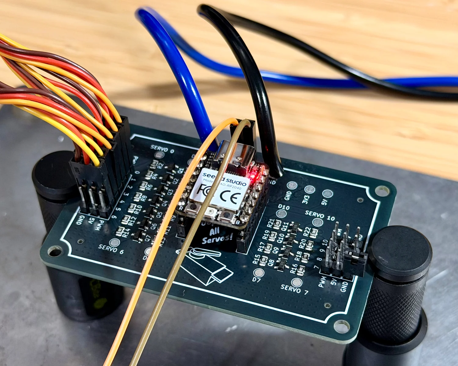
I hooked up the six micro-servos I had lying around near my bench to the Servo 0 to Servo 5 pins to act as an example load. The following CircuitPython snippet sweeps all six servos back and forth every second until the end of time.
from board import D0, D1, D2, D3, D4, D5
from time import sleep
from pwmio import PWMOut

pins = [
    D0, D1, D2, D3, D4, D5
]

pwmouts = [PWMOut(pin, frequency=50) for pin in pins]

while True:
    for pwm in pwmouts:
        pwm.duty_cycle = 2600

    sleep(0.5)

    for pwm in pwmouts:
        pwm.duty_cycle = 6400

    sleep(0.5)
The four blue servos are just some Amazon bunch-a-letters knock-offs, but they seem to keep pace with the branded TowerPro model just fine.
The unlabelled black servo, however, has a noticeable lag in its responsiveness.
With the board now powered from an external supply, we can observe the current passing through the measurement point. Unfortunately, my multimeter is a piece of rubbish, fake scope, the UNI-T UT81B. Even back in 2012, it was getting pretty poor reviews; I agree completely with the sentiment that it's "certainly of no use for any half serious folks looking to do measurements". The refresh rate and lag make it almost impossible to get accurate readings for the peak or instantaneous current, instead it appears to only update once every 0.5 seconds or so and displays an average from over that period.
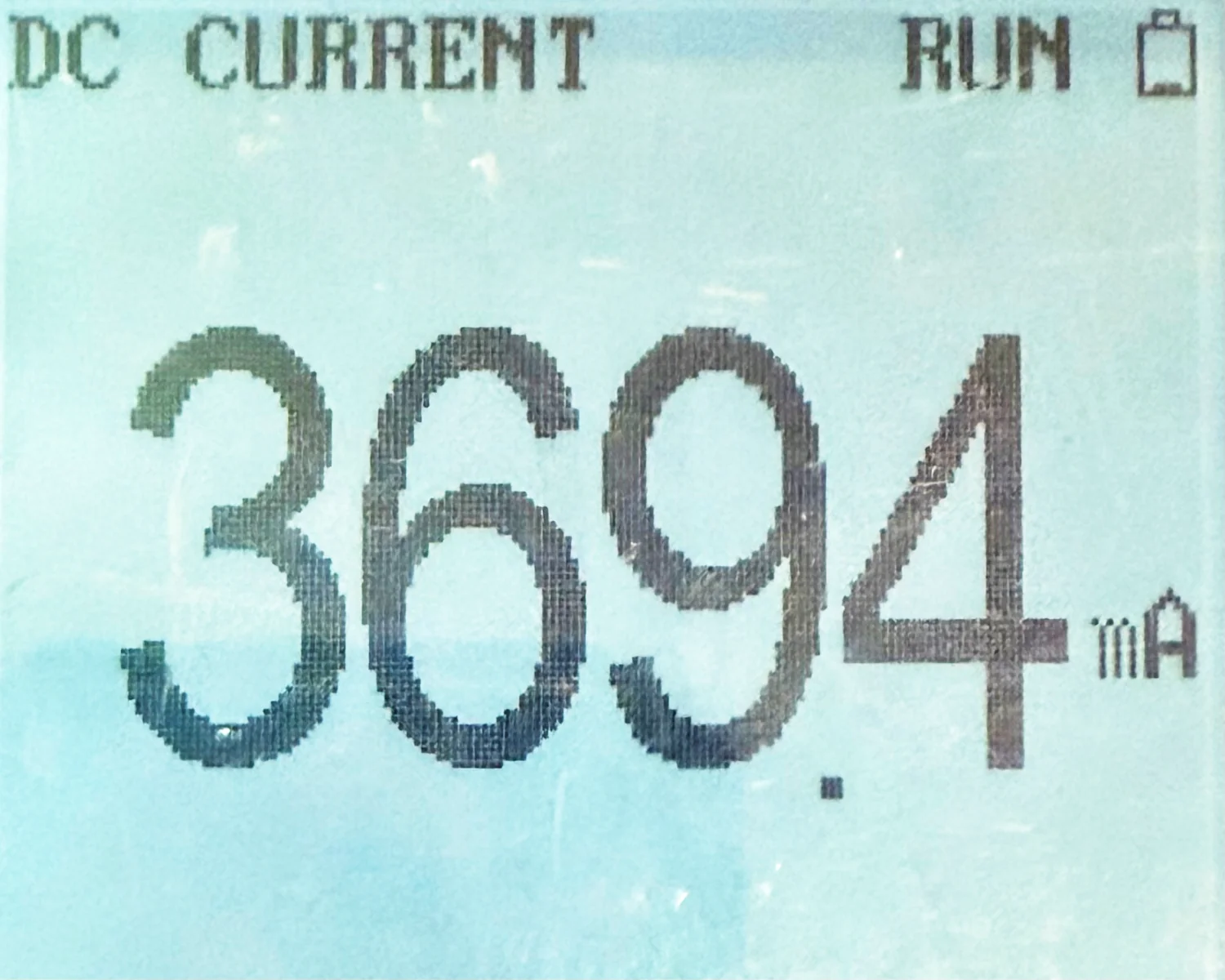
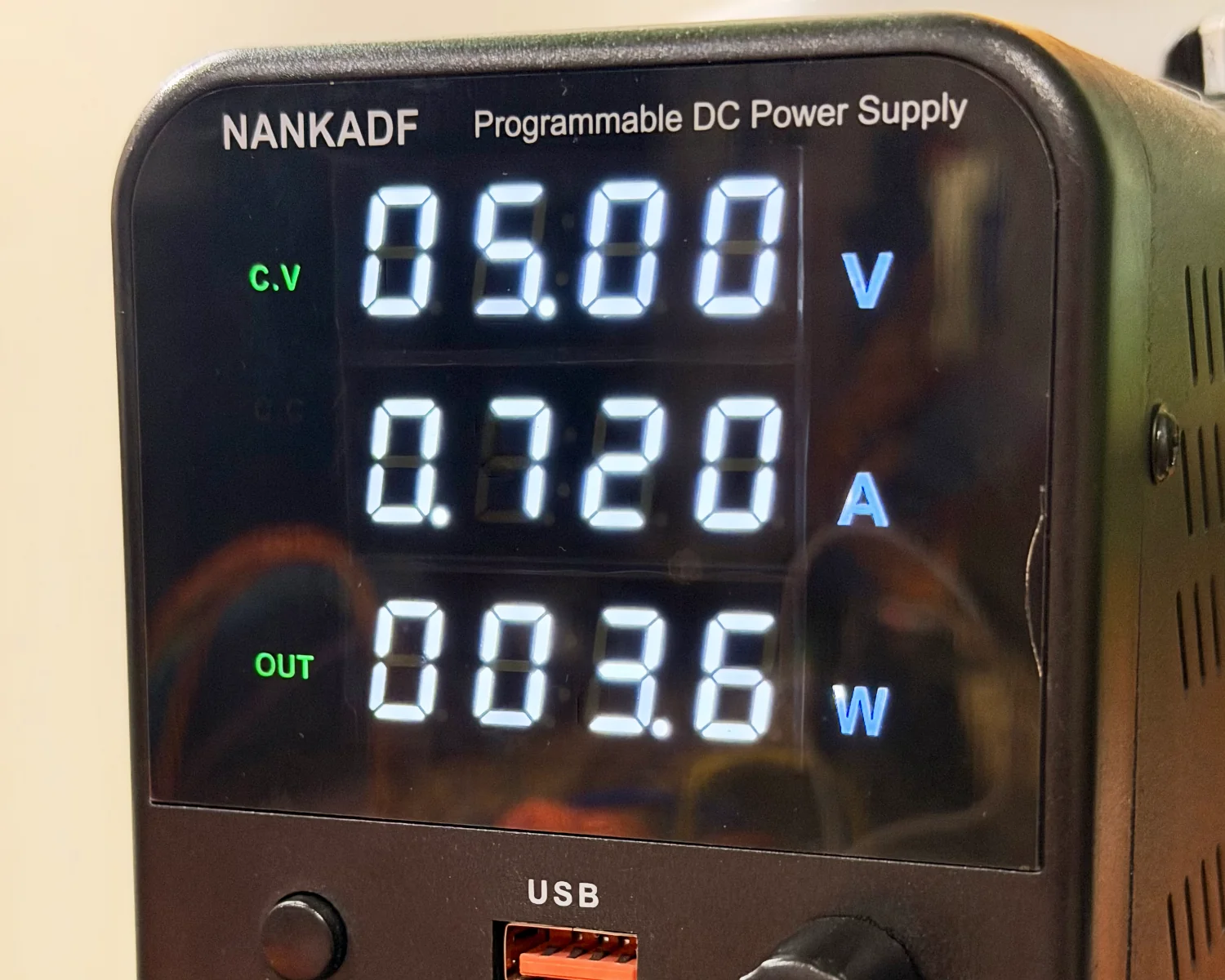
That's still enough to prove to me that the principle works, even if it's not as useful as I'd hoped. Luckily for me, my bench-top power supply already provides current readings at a much more sensible speed.
Pushing the limits
The 5 v and 3.3 v supplies on the XIAO boards are interesting. The ESP32s & RP2040s all run on 3.3 v and their GPIO pins are all 3.3 v too. The only 5 v circuitry on the boards is the regulator to step the 5 v from USB-C down to 3.3 v. This means, if we disconnect the USB-C cable, to prevent back-feeding, we can actually supply a little more than 5 v to the board and suffer no real ill effects.
It's always worth referring to your datasheets, but for the Seeed Studio XIAO ESP32C6, they use the SGM6029C from SG Micro. SG list the recommend maximum voltage for this part as 5.5 v, with an absolute maximum voltage of 6 v. Tower Pro also list performance characteristics for some of their servos beyond the typical 5 v, too. Their MG90D has operating speeds listed for 6 v and claims its operating voltage goes all the way up to 6.6 v.
The following video shows the effect of ramping up the voltage from 5 v to more than 6 v and back down again, while the CircuitPython sketch runs on a loop on the XIAO.
A noticeable change in pitch can be heard in the servo's motors, and a definite change in draw can be seen on my power supply.
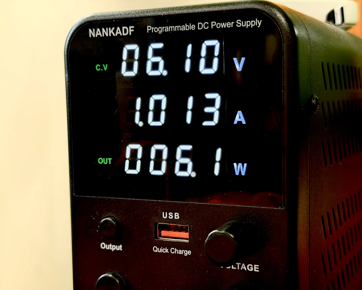
I'm happy that this proves the benefit of running an external power supply, especially when we can see spikes of 1 W per servo motor. If we were to run the same sketch with 11 servos at the same time, it would be easy to routinely draw more than 10 W. That is well beyond what the standard laptop USB port would be capable of providing.
Conclusion
I'm happy that my board design is technically correct, and that my feature set is logically sound. All that's left is to solder together a few more boards, take some product shots and list them up on my Lectronz store.
2026-08-10