Building Oops! All Servos!
This article includes sponsorship or links with referral codes which will earn me an affiliate fee. These are clearly marked with a 💵 symbol.
As described in my previous post, the Oops! All Servos! is an expansion board for Seeed Studio XIAO and Adafruit QT Py microcontrollers, with JR-style servo headers on all 11 GPIO pins. Each pin also has a bidirectional 3.3v-to-5v level shifter, and the board has external power input including a current measurement point. The development of Oops! All Servos! has been sponsored by JLCPCB💵.
Even though this product's development was sponsored, I still wanted to save some money, so I opted to handle sourcing and fitting the through-hole components myself. I used JLCPB to make the boards and had them tackle the smaller surface-mount components for me. When I placed the order, I also deliberately ordered a few unpopulated PCBs to use as assembly jigs.
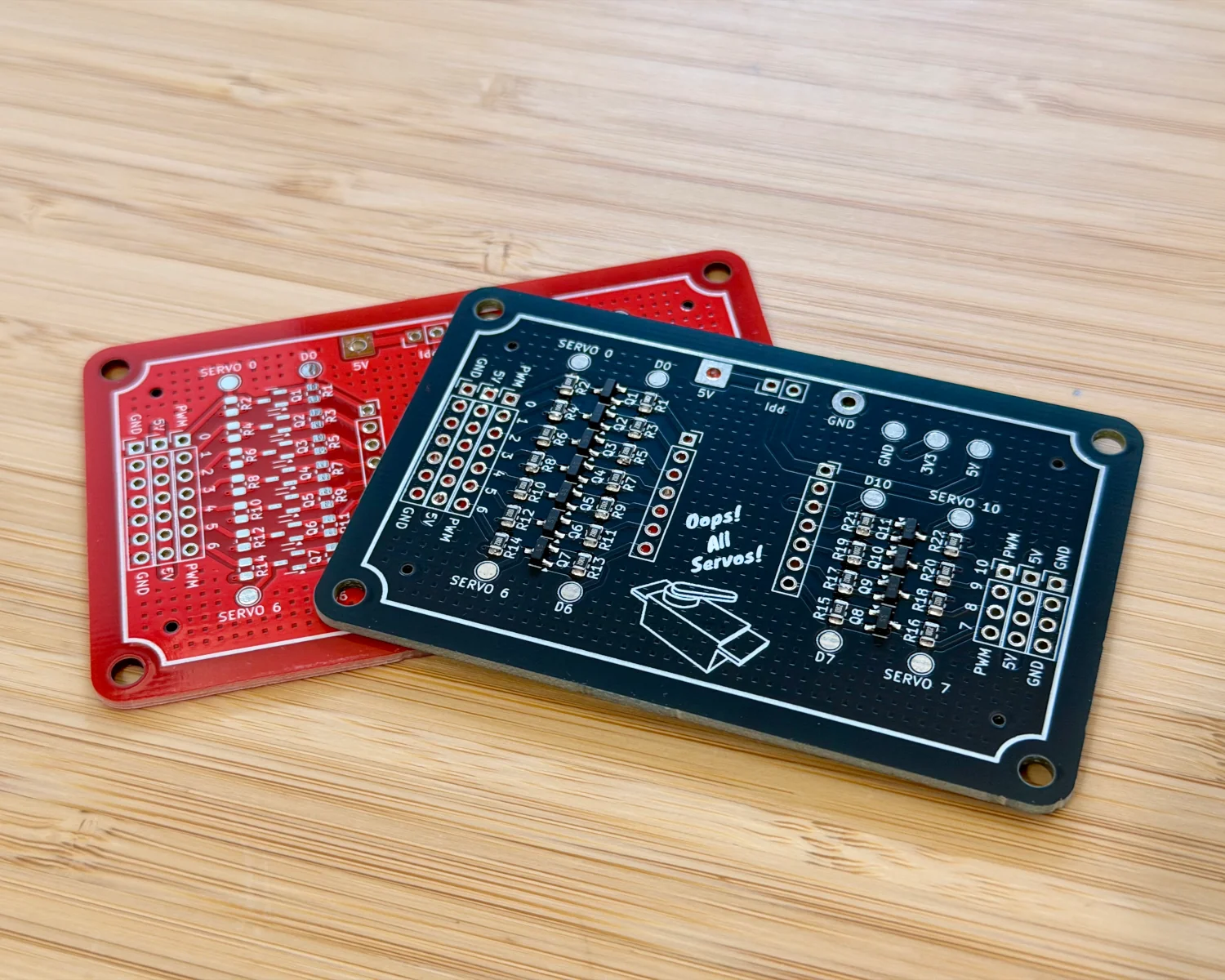
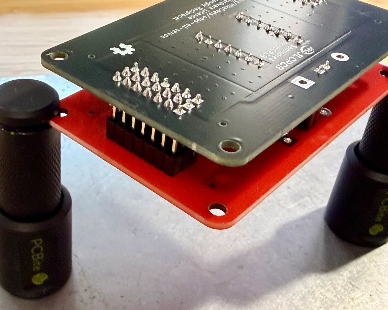
A rudimentary through-hole jig can be made by flipping an unpopulated PCB over and using sockets in place of pin headers and vice versa.
Over the past couple of months, I've been testing out InvenTree, a locally hosted inventory management system.
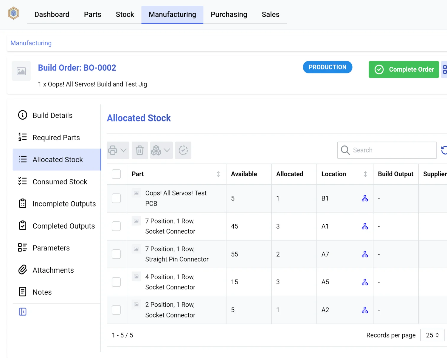
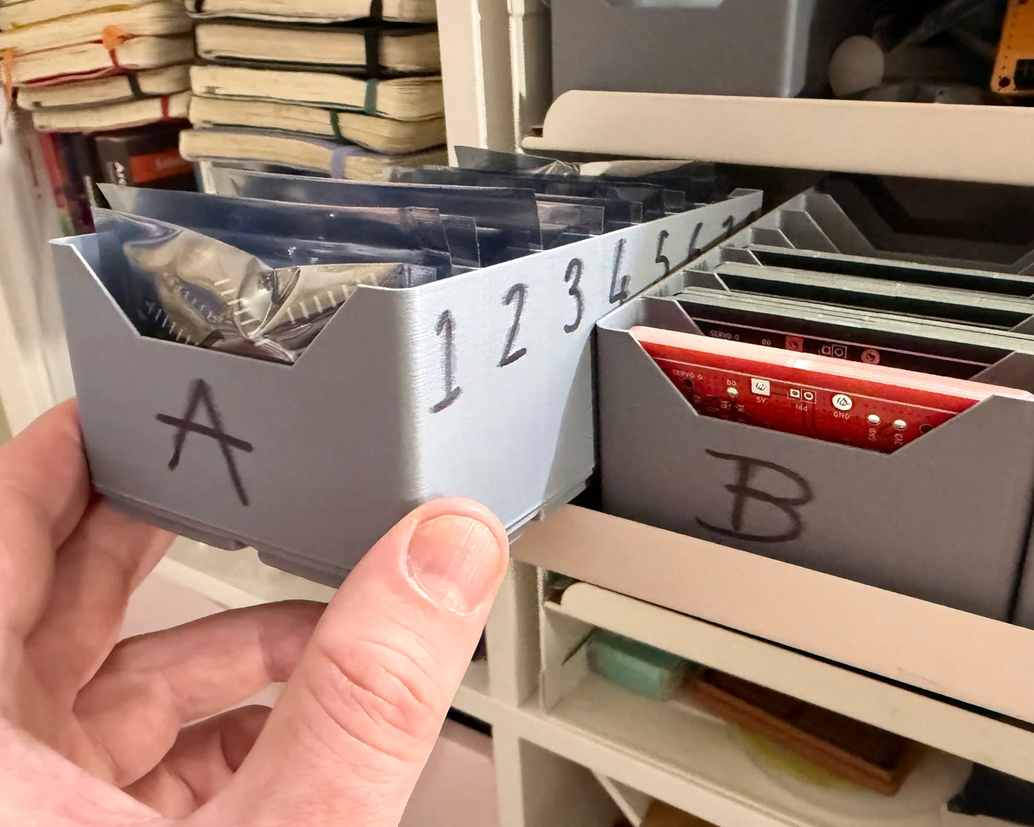
These Oops! All Servos! boards are the first batch of products I've manufactured since starting using InvenTree. There are probably manuals and documentation available online, but it's really pretty intuitive, and so far I've managed to muddle through without needing to refer to them. The InvenTree team is also on Mastodon, so go say "Hello!" if any of this sounds good to you.
The picklists it produces as part of the "build order" process are really useful. It takes a little effort to receipt your deliveries and collect everything into correct inventory locations, but the effort pays off. I no longer need to dig through my stack of Mouser and Digikey packages to find the parts I need.
With my latest delivery of parts and boards in hand, I created a build order for a jig and another for a full board, then fired up my soldering iron.
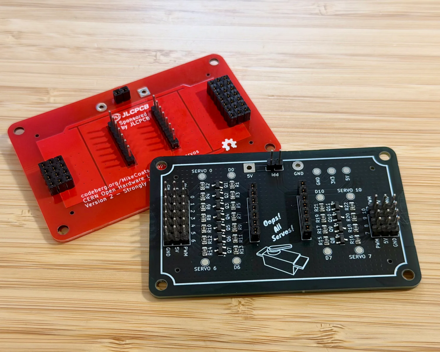
A few minutes later and we've our first jig and board assembled. The first time you put all the components together can take a little while (and a not insignificant amount of jiggling and swearing) to line up all the pins, but this is a one-time pain. For later boards, the jig works a real treat, and everything now lines up perfectly.
With the boards assembled, I can now test fit a microcontroller to check my clearances and start functional testing.
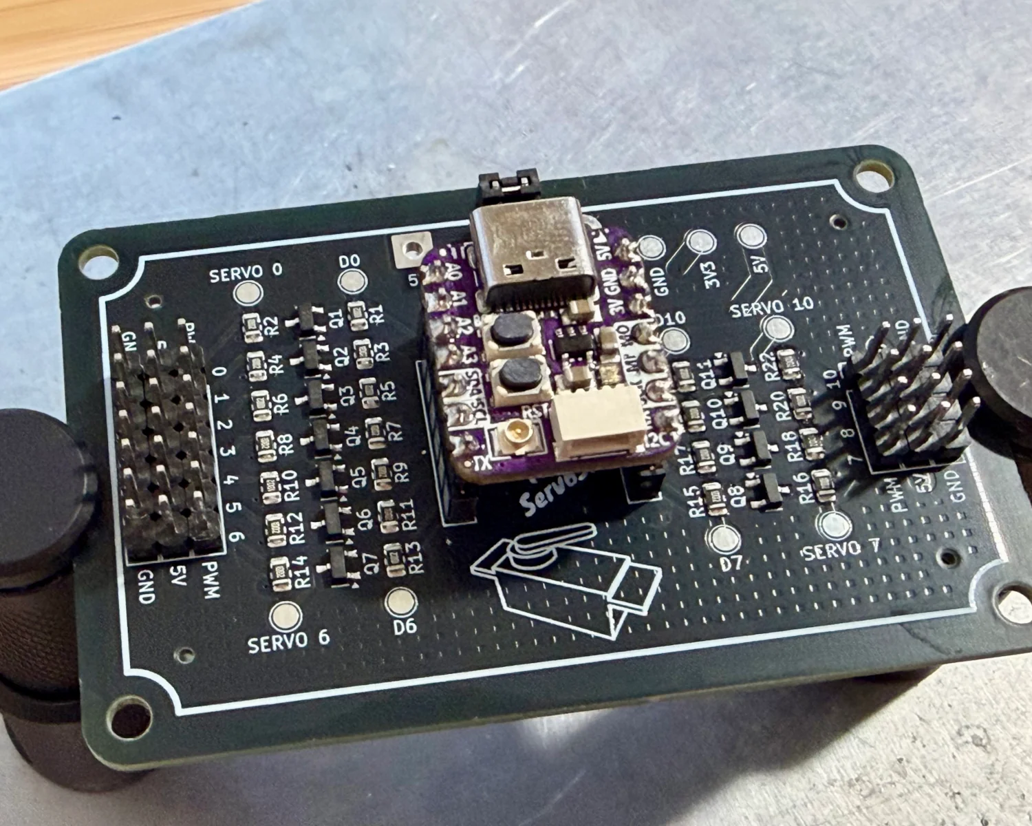
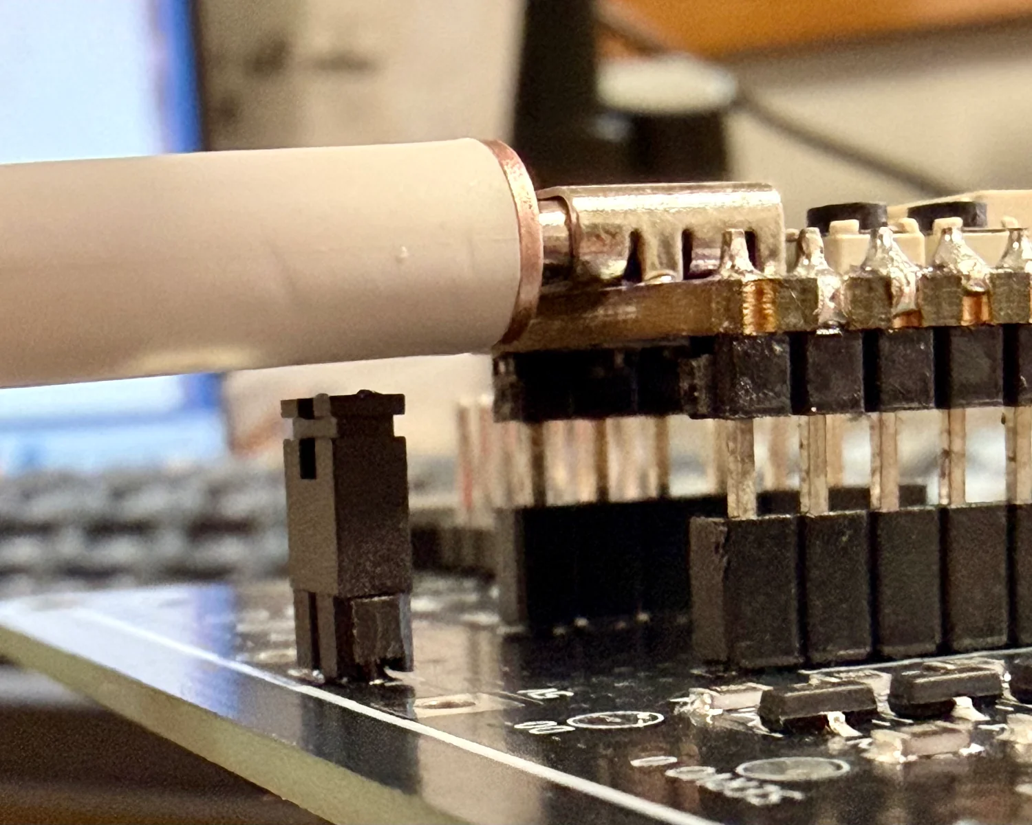
Here we can see an Adafruit QT Py fits perfectly, so I know the centre-to-centre distance between my SIL sockets is correct. Next up is a test of the USB-C connector. Here we have an (allegedly) 240-watt USB-C cable, with space above the current measurement header. The clearance is a little closer than I’d have liked, but still fine.
Next on my list for testing is the MOSFET level-shifters.
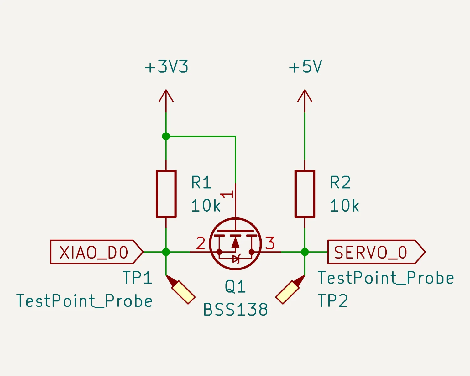
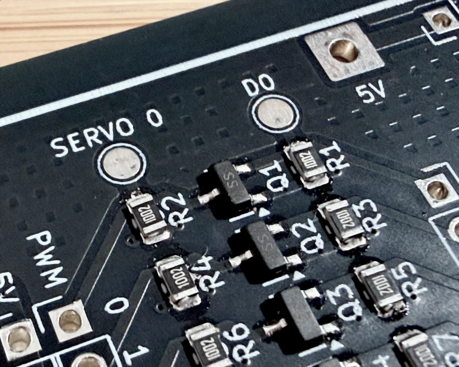
I can never seem to get the dozen or so variations in Gate, Drain and Source layout and footprints straight in my head, so this was going to be the most critical part to test.
Did I get the level-shift topology right? Did I get the MOSFETs’ pinouts correct?
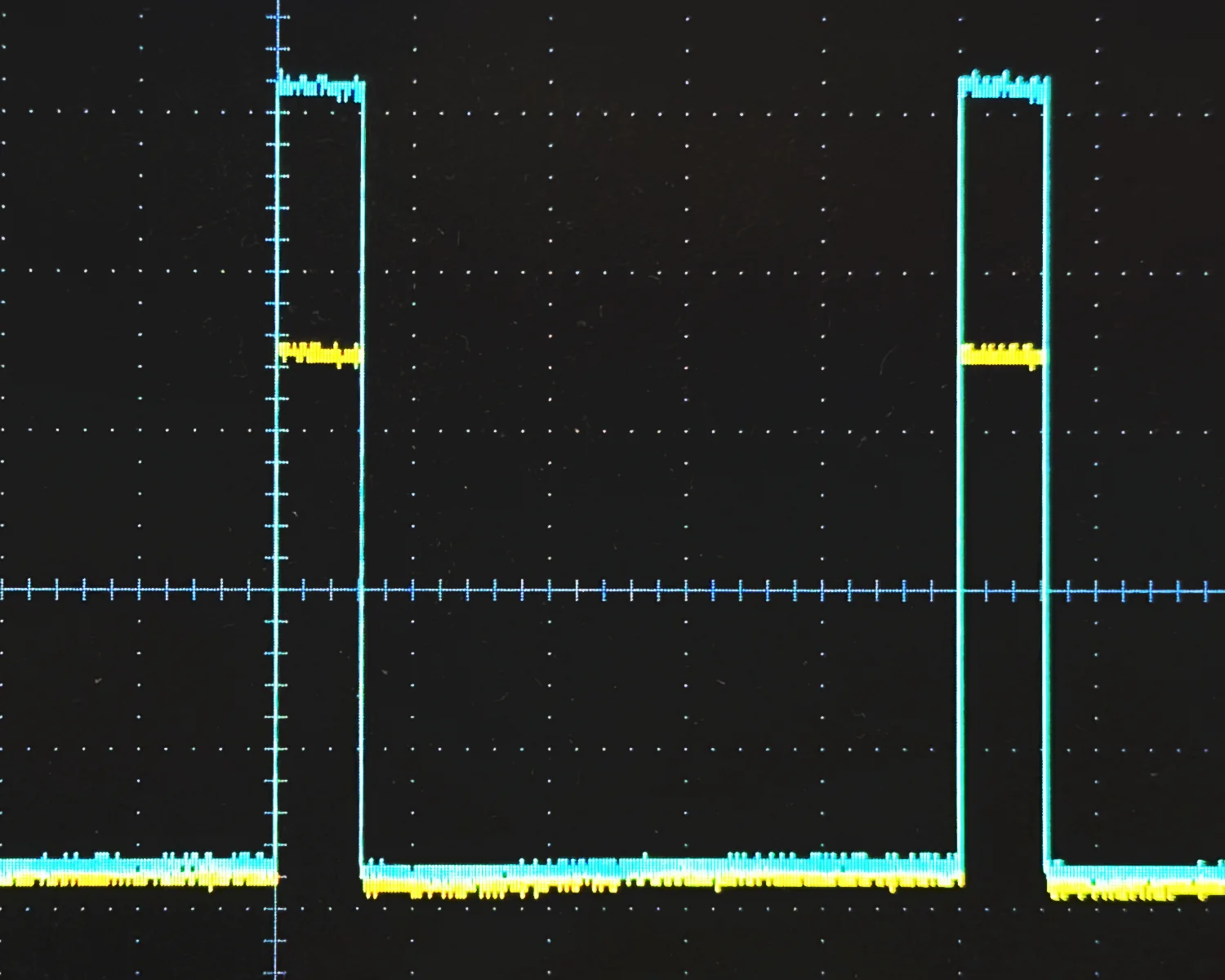
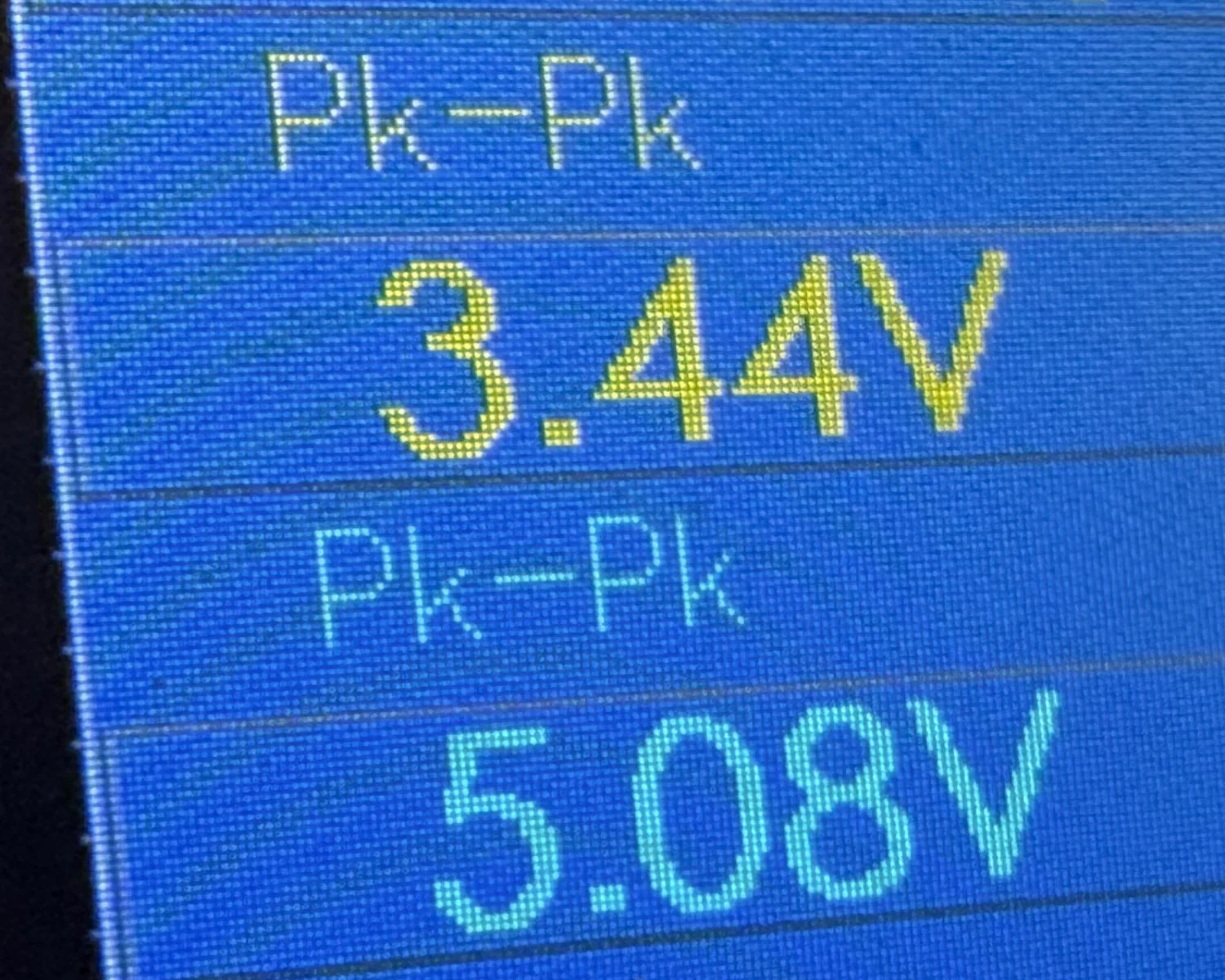
Running a small CircuitPython program, I can fire some PWM through the QT Py's GPIO pins and hook up my oscilloscope to test the output. Here we can see some short pulses leaving the GPIO pins at 3v3 with corresponding 5v pulses on the other side of the MOSFETs at the servo pins. That’s a relief!
That's enough for today, but there are still many more tests to be done.
- The level shifters are supposed to be bidirectional, so I still need to test 5v inputs being brought safely down to 3v3.
- I need to test hooking up an external supply and testing out the current measurement header.
- I think I've got about six micro-servos in stock, so that will be a decent test, but I'd like to try running a full complement of 11 possible servos and observing the current draw.
2026-08-03