Reverse Engineering a VanMoof e-shifter – Part 2 – Decoding the Signals
At the end of the last post, I left everyone hanging, having tapped into and sniffed some data being transferred on the wires between the bike and the e-shifter. The questions to answer were:
- Is the bike the requester, or is it the responder?
- What speed and format was that data?
- What messages are being transmitted?
The reliability of this e-shifter in the X3 and S3 has been argued as the cause of the failure and eventual bankruptcy of VanMoof. If I can decode these messages, I have the opportunity to build a replacement module that could spoof the original e-shifter.
This component fails and has failed for many owners, and historically this failure occurred during the bike's warranty period. It's been suggested that VanMoof provided so many replacements that they used up their entire stock and were unable to make or sell any more bikes. We've had the e-shifter fail and be replaced twice on our bike since owning it. I really need to come up with a solution before it fails again.
Now, on to the reverse engineering!
Is the bike the requester, or is it the responder?
On the oscilloscope, we could see that a request appears to be sent on one wire and a response is received on the other.
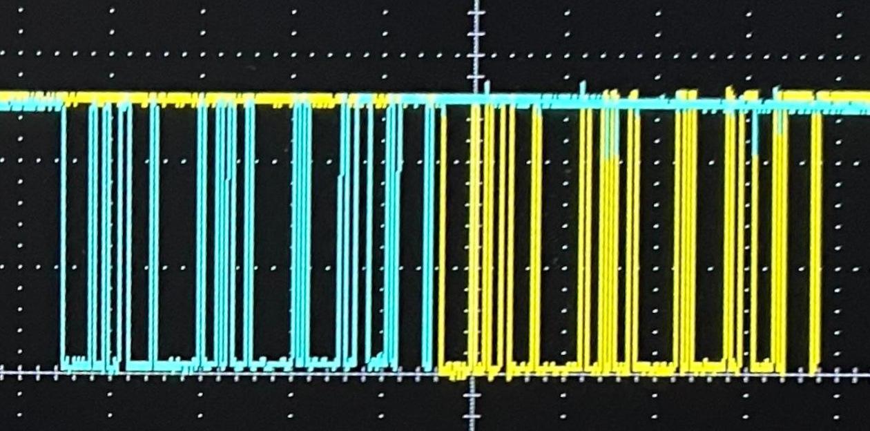
By removing jumpers from the data lines on the Spy! Break! Inject! we can determine which side asks the question and which side responds.
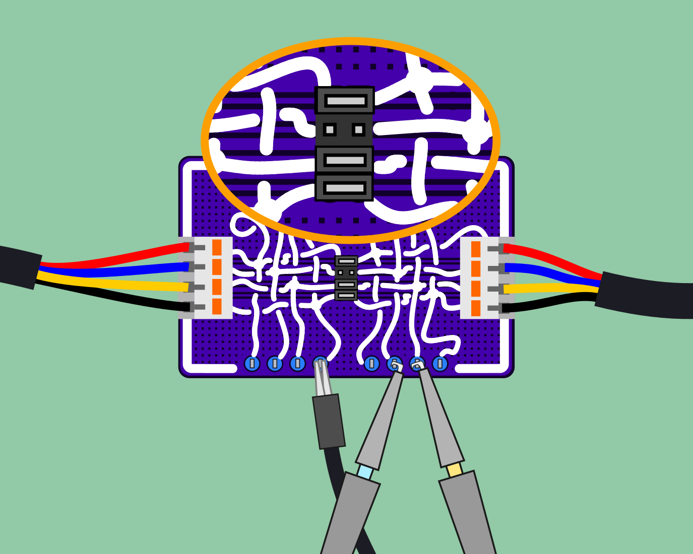
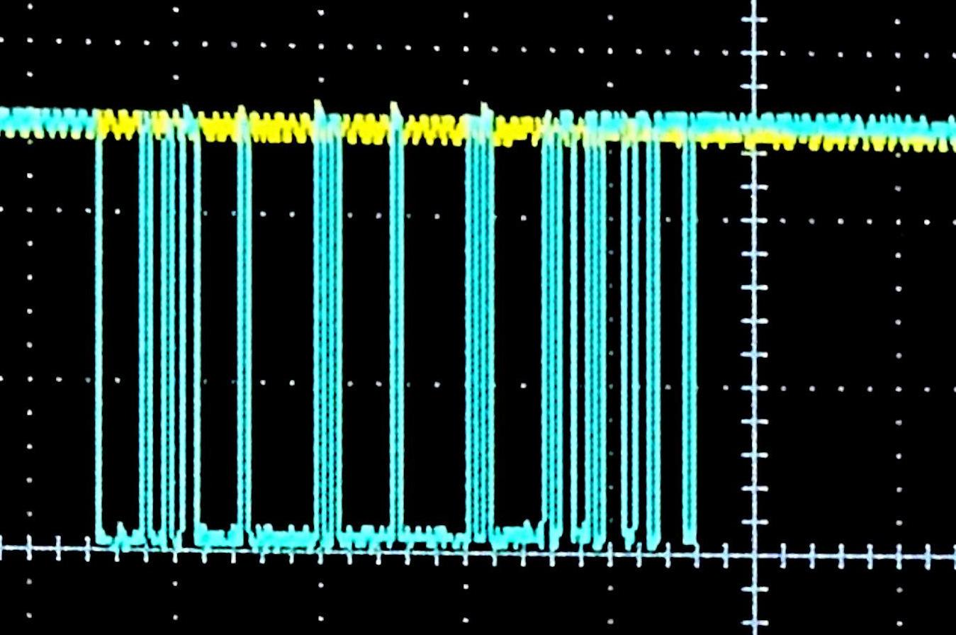
Here we see that the bike's responsible for asking the questions and, with no signals being received by the e-shifter, no responses are generated and transmitted.
What speed and format was that data?
Using the right-angle pin headers on the Spy! Break! Inject!, we can hook up a logic analyser like a Glasgow Digital Interface Explorer.
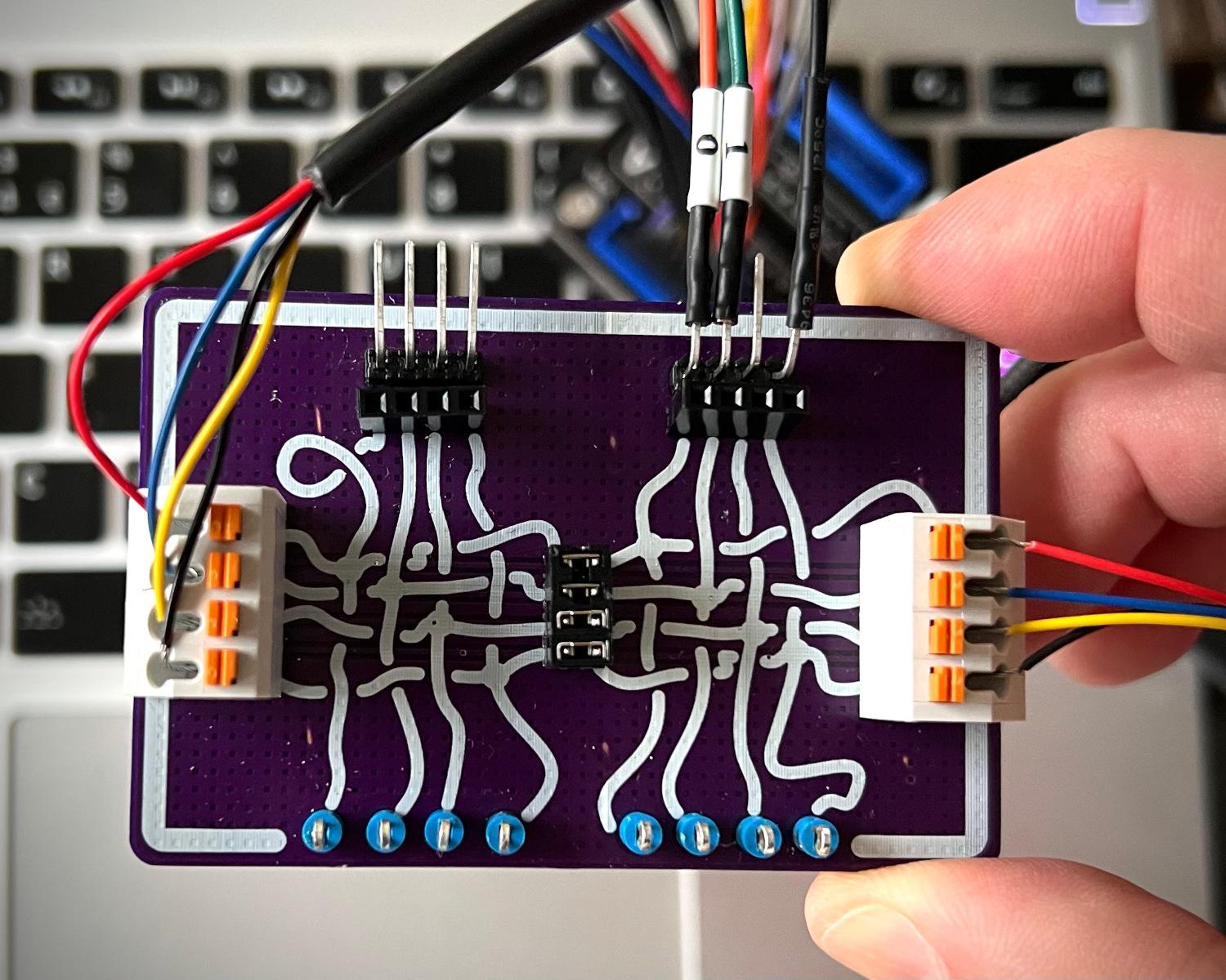
With the Glasgow in place, we can capture the data being sent between the bike and the e-shifter. That capture can be opened in GTKWave for visualisation and measurement-taking.

Zooming in on the stream of data allows us to identify individual packets.
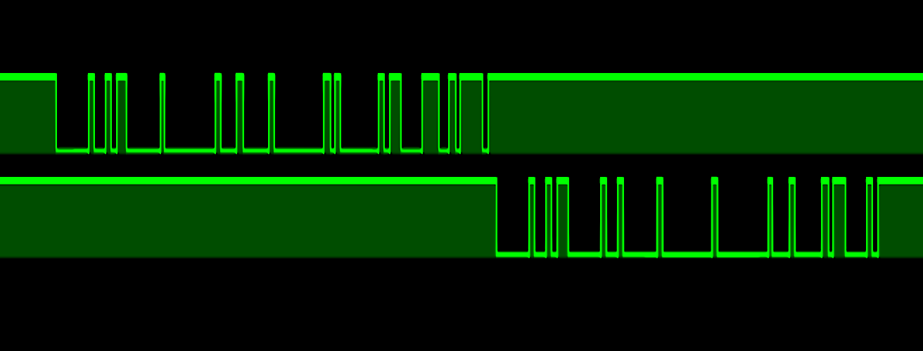
Zooming in further, we can see individual bits in the data stream. The on-transition of this bit is a little noisy, but we can still use it as the basis of our timing calculations.

The total time from the first spike of the bit turning on until it turned off again was 104,187 nanoseconds. Inverting that period to a baud rate gives us 9598.13, or as damn near as 9600 bps as we'd expect to find. Zooming back out again, we can see the question packet lasts 8,380,458 ns and the response packet is 7,279,542 ns long. Taking a bit as ~104,000 nanoseconds, that means a question packet is ~80 bits long and the answer packet is ~70 bits.
Assuming both of our question and answer packets use the same framing, the greatest common factor of 70 and 80 is 10, meaning our question is likely made up of 8 bytes, each 10 bits long, and our answer is 7 of these 10-bit bytes. 10-bit bytes seem silly until you think about serial UART framing. Commonly, UART frames will begin with a start bit, then all the data bits, then an optional parity bit and between 1 and 2 stop bits. One of the most common UART framing is 8-N-1, or 8 bits of data, no parity bits, 1 stop bit. Taken with the mandatory start bit, you get to 10-bits transmitted per byte, confirming 8 bytes for our question and 7 bytes for our answer.
What messages are being transmitted?
Guessing that our data is in 9600-8-N-1 format, we can use PulseView to decode the captured signals in to the bytes transmitted.

The request packet is decoded to 0x20, 0x03, 0x00, 0x01, 0x00, 0x01, 0xD3, 0x7B and the response is decoded as 0x20, 0x03, 0x02, 0x02, 0x00, 0x05, 0x23.
Any time I see bytes repeated at the start of several packets, it sets off my spidey-senses that we're looking at common headers or addressing information.
Similarly, a series of "low" or "small" bytes such as 0x00 and 0x01 followed by some unusually high values like 0xD3 or 0x23 screams out "checksum" to me.
Searching the web for "16-bit checksum" and "16-bit CRC" led me to the CRC Calc website.
Dumping the first 6 bytes of the request packet in to their form and selecting CRC-16, gave a list of possible checksums.
Searching within the results table for D3 and 7B highlighted the CRC-16/MODBUS row, although it presented the bytes as 0x7BD3 as opposed to 0xD37B which we expected based on what we saw within PulseView.
Now we think we're probably dealing with Modbus, we can do some research and try to understand the rest of the "conversation".
Wikipedia has an article on Modbus including a section on Modbus RTU, which appears to match the data we're seeing.
According to that page, the checksum is transmitted least-significant byte first which means the CRC Calc site was correct, 0x7BD3 is the checksum, but it is transmitted as D3 followed by 7B.
PulseView can be leaned on again to interpret the Modbus packets and reveal their contents.

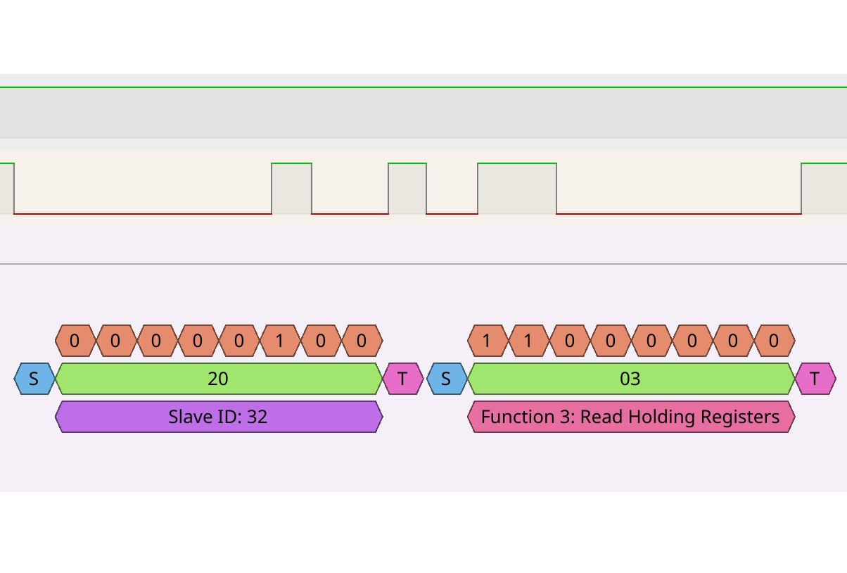
This conversation appears to show a controller asking a peripheral device with ID 32 (0x20) a question, and a peripheral device with ID 32 sending an answer.
Digging in to the question packet, we can see more details.
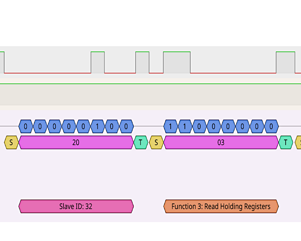
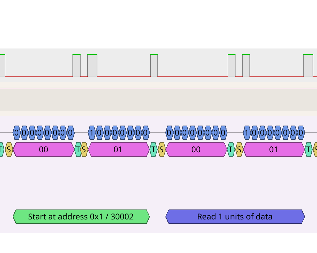
The question appears to be to "read a register", starting at address 0x0001, reading 0x0001 units of data.
We can also look more closely at the answer.
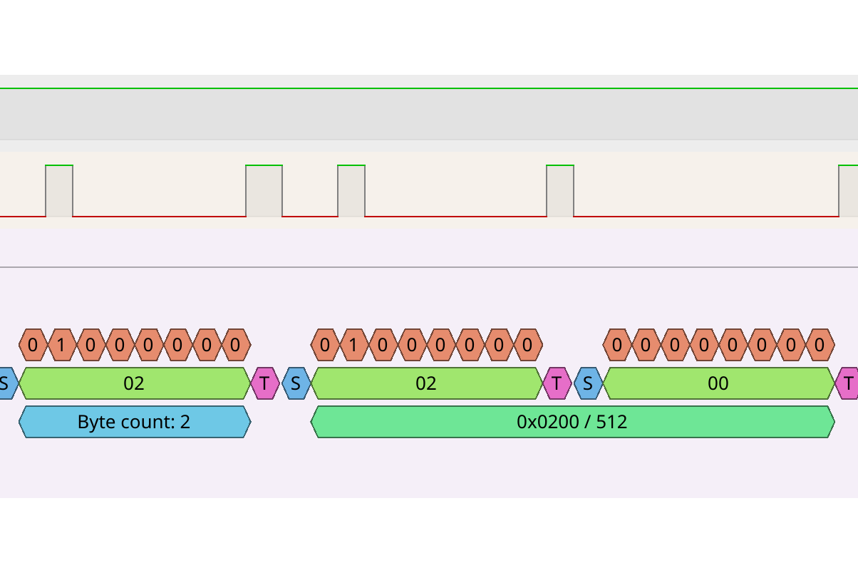
Here, we can see a response indicating that our peripheral device has read a register, returning 2 bytes of data, 0x0200 or 512.
What is in register 0x0001 and what does a value of 0x0200 mean?
Who knows?!
Do we even need to understand the communications, or will rote repetition of prerecorded packets be enough to fool the bike?
In my next blog post, I'll detail a small project that can log an entire bike ride's worth of communication. Hopefully we can attempt to analyse the messages, or we can at least learn to spoof the correct responses to the bike's requests.
2025-01-15