Reverse Engineering a VanMoof e-shifter – Part 1 – Connectors and Connections
Anyone who's followed this blog for a while will know that we own a VanMoof e-bike, and we have a love/hate relationship with it due to its reliability. The most common and dreaded complaint for VanMoof owners is "Err 44". Error code 44 on a VanMoof X3 or S3 means that the bike cannot communicate with the e-shifter and gear shifting will not be available.
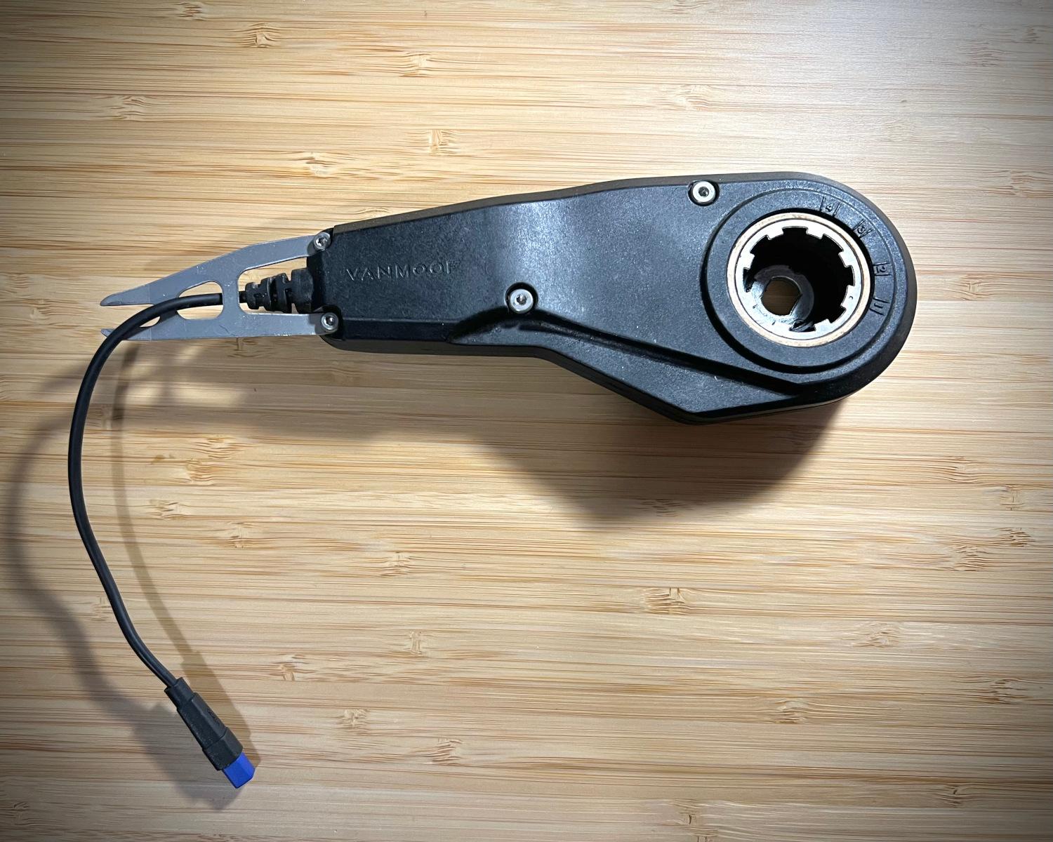
VanMoof really tried to be the "Apple" of e-bikes, and their e-shifter is part of that. Instead of producing a single-speed bike with no gears or a traditional manually shifted bike they built a bike with an automatic electronic gear shift. At certain speeds the bike will automatically shift gears, giving its rider more torque to get going from a stand-still or more speed once the bike was moving along.
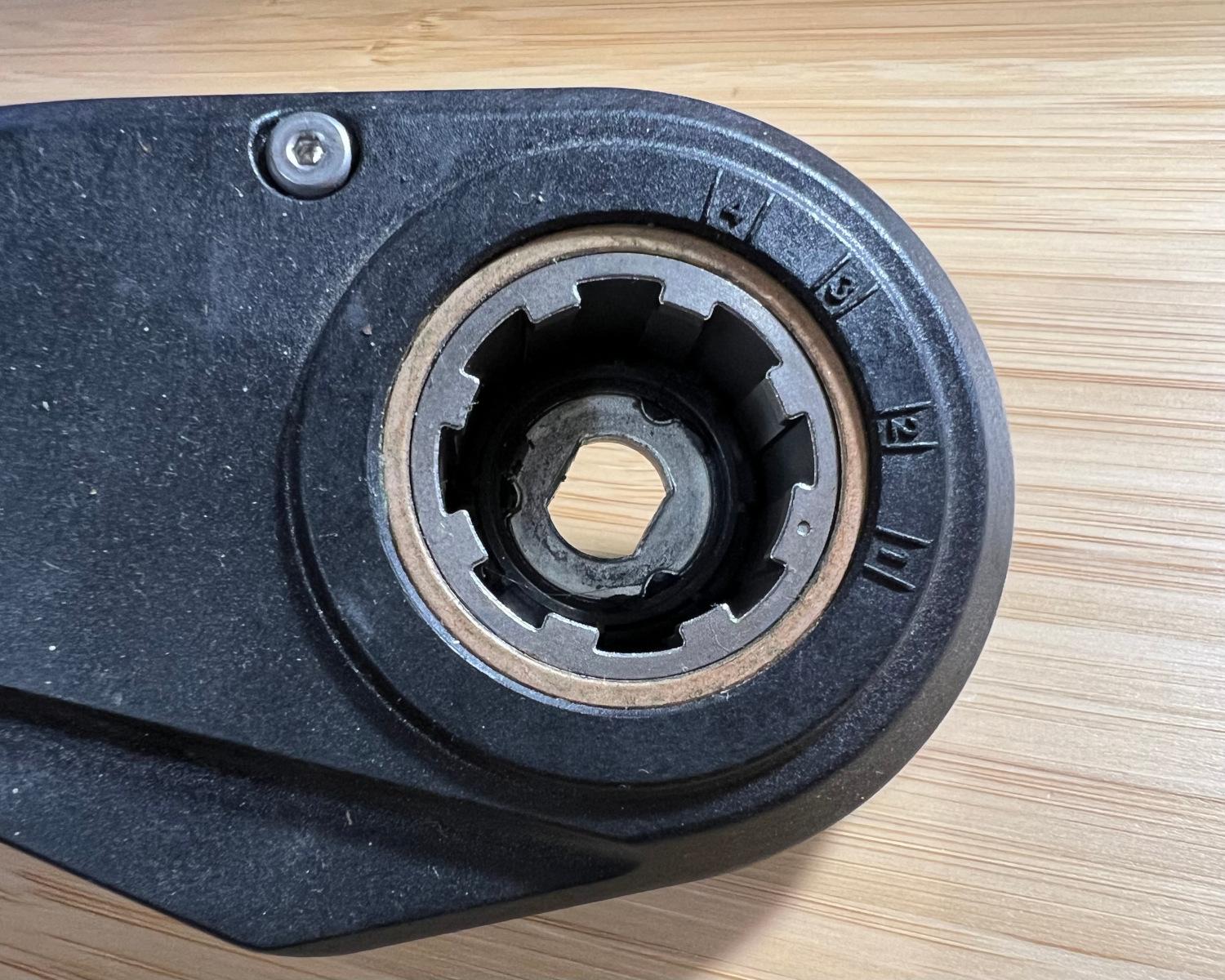
If I can reverse engineer the communications between the bike and the e-shifter, I should be able to build a replacement module that spoofs the original. The gears in the bike's Sturmey Archer hub can be manually, and semi-permanently, set if the broken e-shifter is removed from the bike. The e-assistance, up to 15.5mph from the electric motor, and the boost button, giving 100% motor power from a stand-still, means the bike is still perfectly usable if it's manually shifted in to 3rd gear. Whether broken or removed, the bike will complain that it cannot communicate with the e-shifter and present "Err 44" whenever the bike comes to a stop.
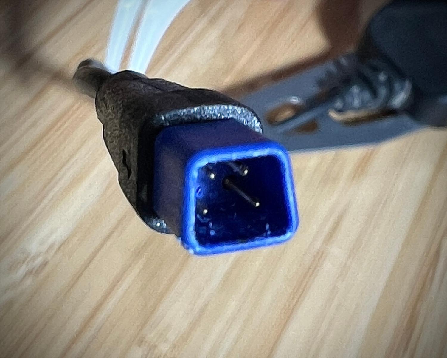
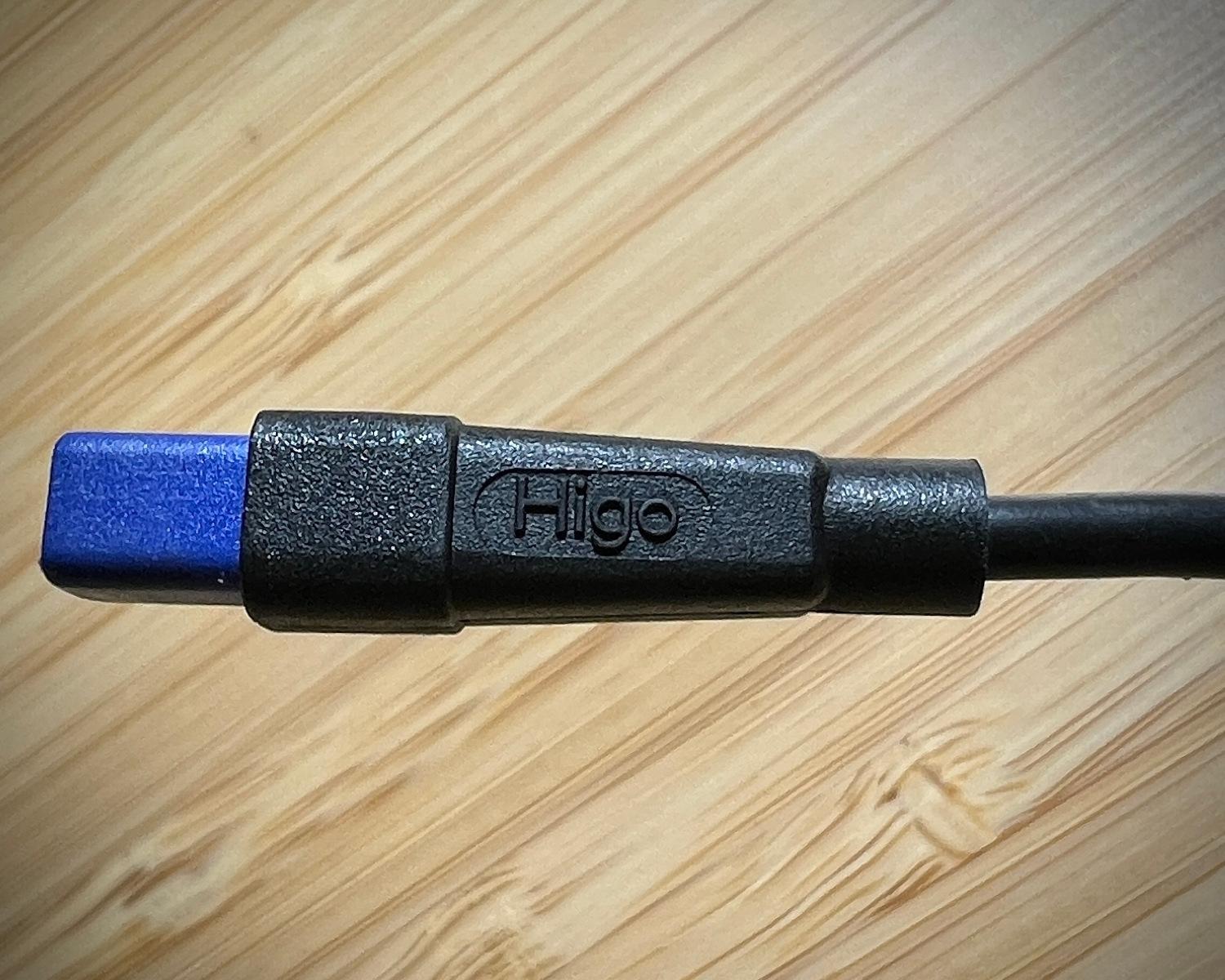
The e-shifter has a 4 pole, trapezoidal connector, in blue plastic, with the word Higo written on the side. Searching for Higo e-bike connectors returns results for the Chinese company HIGO who specialise in waterproof connectors and harness system. It seems they've partnered with A&C Solutions to act as their European distributor, running the higoconnector.com website. A PDF catalogue on the European site includes our connector on page 24 and the order code we need to buy some.
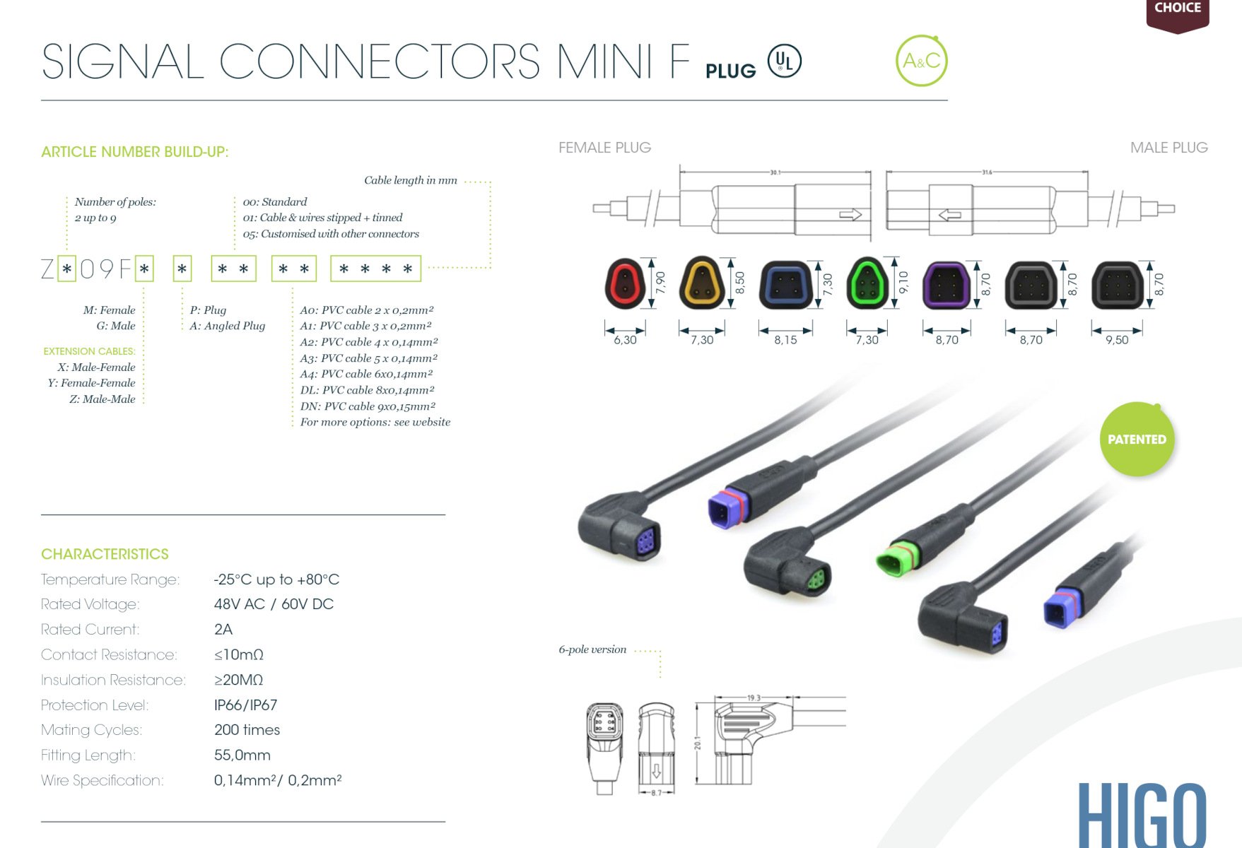
Calculating the codes Z409FM and Z409FG from the brochure, we can now search for those connectors and luckily find a German shop selling both the socket and the plug we need.
Reinhard from e-bike-technologies was excellent, arranging the international shipment on the same day, and my delivery arrived within 4 days.
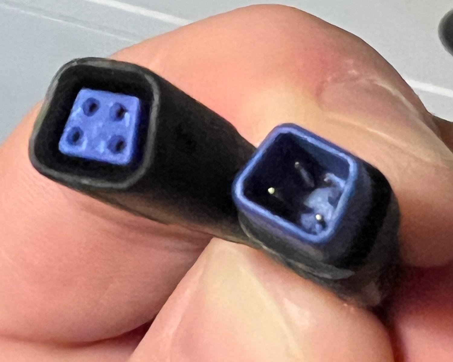
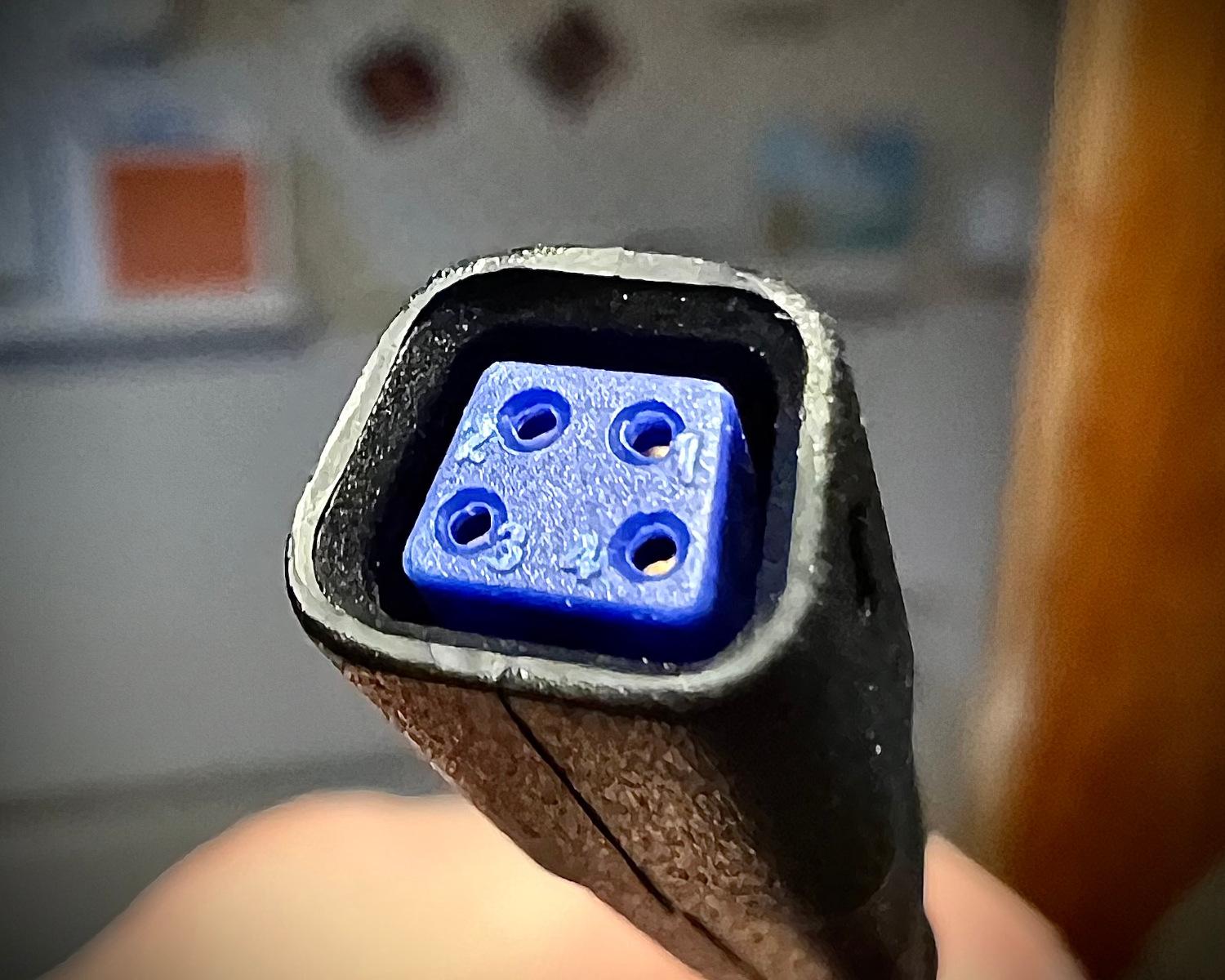
With the new connectors in hand, it's possible to connect them to a Spy! Break! Inject! and use a multimeter to test for continuity. We can therefore determine how the pin numbering of the connectors matches up to the 4 coloured wires within the cable.
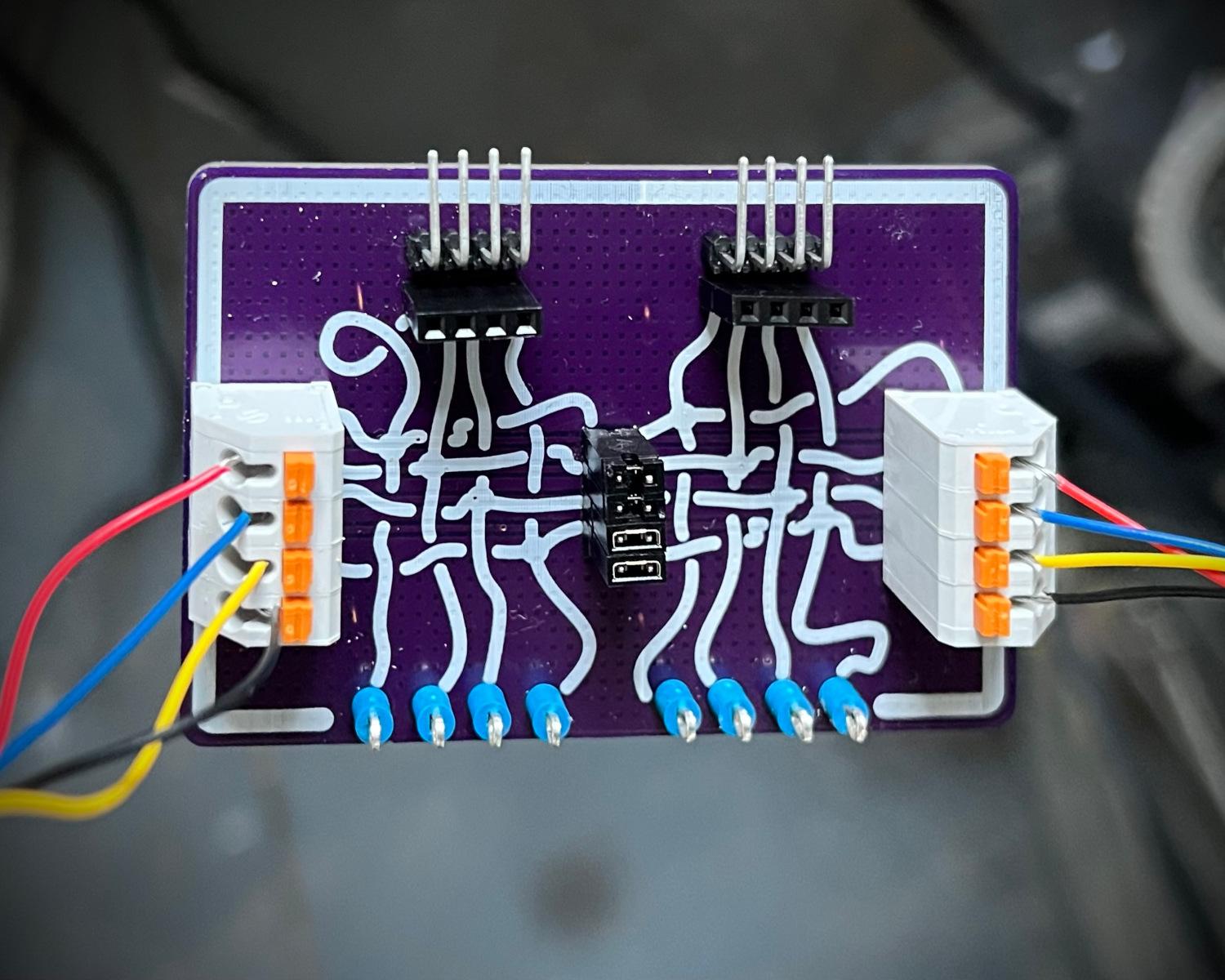
| Pin Number | Wire Colour |
|---|---|
| 1 | Black |
| 2 | Yellow |
| 3 | Blue |
| 4 | Red |
Now we've wired a Higo plug and socket to a Spy! Break! Inject!, we can insert our assembly in-line with the bike and e-shifter. Powering up the bike and probing between the test points on the Spy! Break! Inject! lets us explore the voltages available between the wires.
| Wire | Voltage |
|---|---|
| Black | 0v |
| Yellow | 24v |
| Blue | 5v |
| Red | 5v |
At first glance, finding 24v on the yellow wire is surprising. On reflection, the e-shifter is "mechatronic", so having the extra power available makes sense. A higher voltage would make it easier for the motor to physically shift gears. Having two 5v lines is interesting. These could be VCC and some bidirectional data for the microcontroller, or it could be the TX and RX lines for communication.
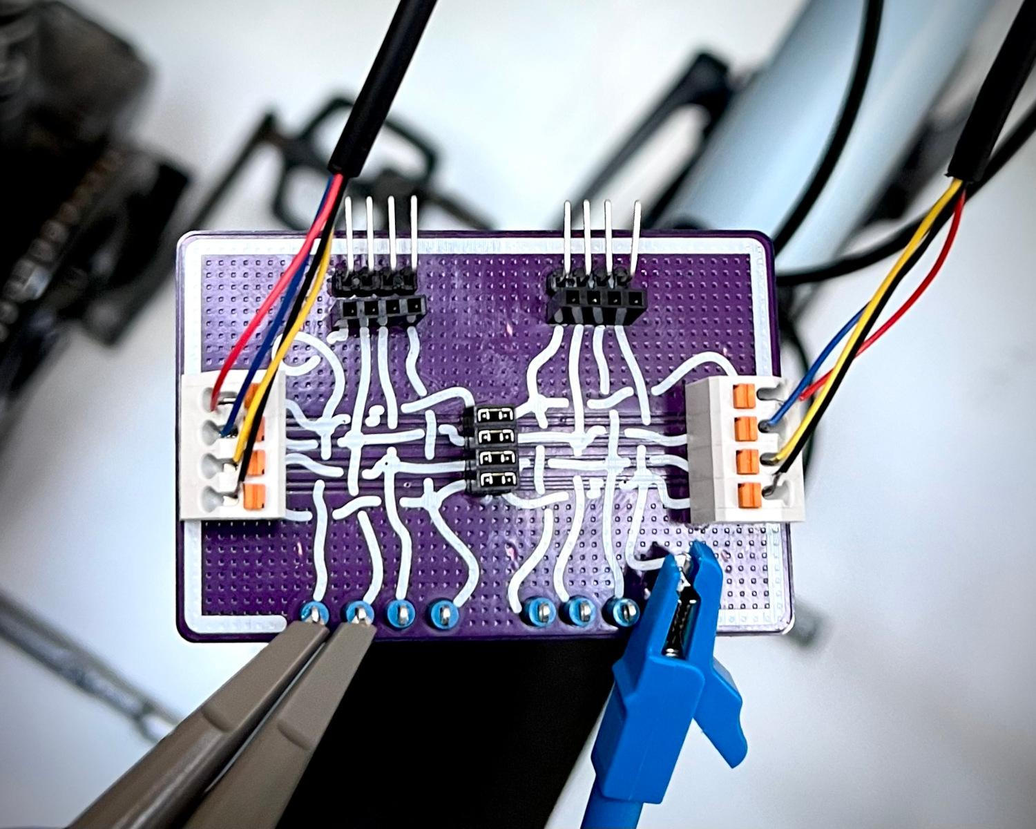
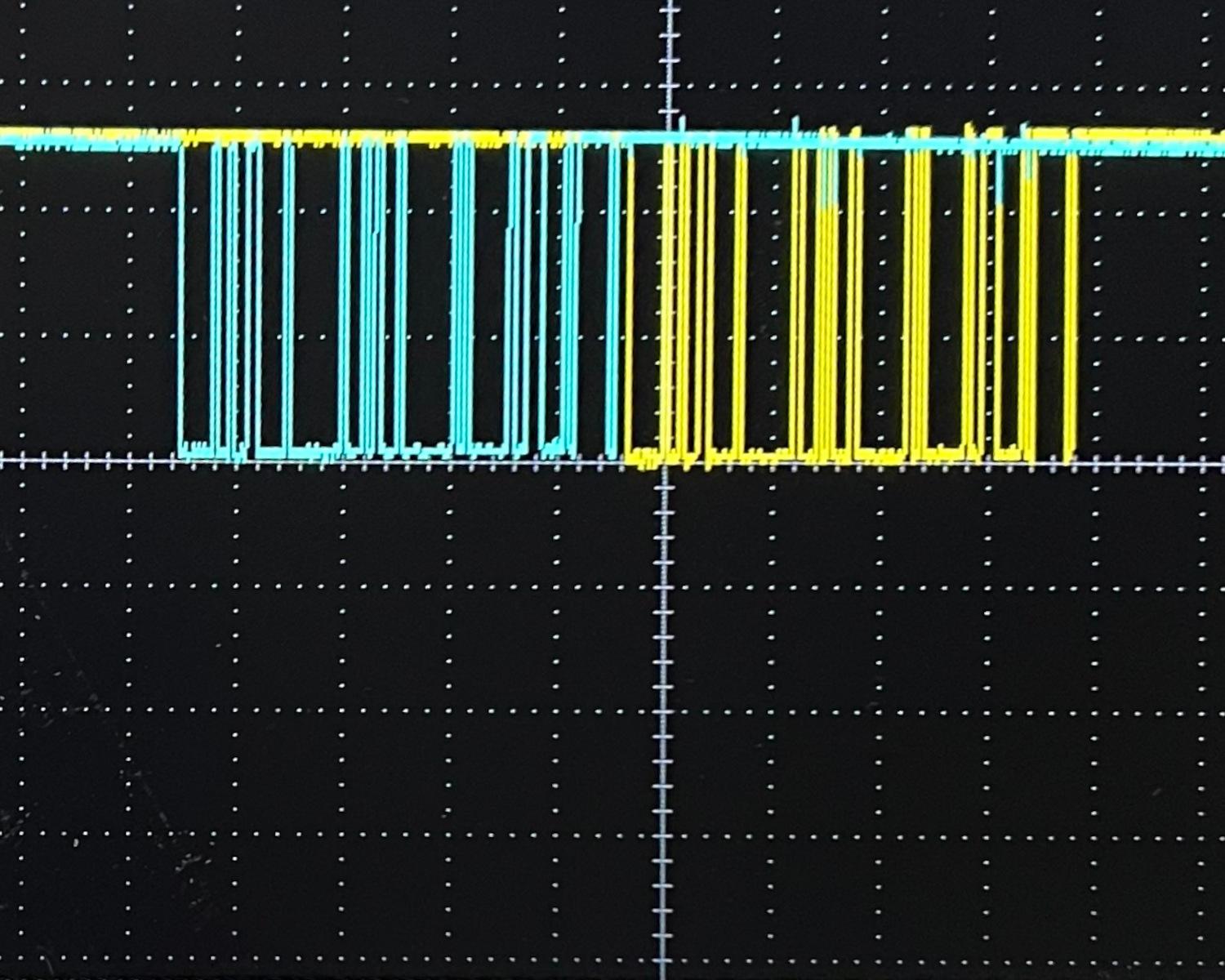
Clipping an oscilloscope to the two 5v lines reveals data on both, apparently in a request and response pattern.
Is the bike the requester, or it is it the responder? What speed and format is that data? What messages are they transmitting? All these questions and more, answered next time!
2024-12-15