VanSpoof - Prototype 1 - Firmware
Last time, we built a prototype PCB. This time, let’s take it to blinky!
All the code in this post, and the extra project files needed to build and flash it, can be found under the prototype-1 tag on my Codeberg repo.
The first thing we need to do is set up our environment. Since this is a firmware project, rather than software, we need to be a bit stricter with how we write our code. We want to prevent ourselves from doing unsafe things, and we need to tell the compiler that we’re running on a microprocessor without a traditional main function or a full standard library. We also want to allow an (incorrectly flagged) unused import as this is how we import our panic handler during debugging.
#![deny(warnings)]
#![deny(unsafe_code)]
#![no_main]
#![no_std]
#![allow(unused_imports)]
We import a number of crates here, the most important being our STM32’s HAL. We’re using a low level HAL, specific to our chip, to prevent us from trying to use features or peripherals that aren’t present on the physical device but might be on others in the range.
// Gives us access to our hardware features; timers, gpios, usarts, etc.
use stm32g0xx_hal::{
    stm32,
    prelude::*,
    serial::{BasicConfig, StopBits},
    time::{Bps, MicroSecond}
};

// Punt Unicode strings out over the usart.
use core::fmt::Write;

// We need to block on our timer `wait`s, so that we actually "wait" for them.
use nb::block;

// Use RTT for debug messaging, including panics.
use panic_rtt_target as _;
use rtt_target::{rprintln, rtt_init_print};

// `main` is our entry point.
use cortex_m_rt::entry;
Next, we need to get our code up and running and start accessing our chip’s peripherals.
#[entry]
fn main() -> ! {
    // Initialize our debugger, all our potential panics go through it.
    rtt_init_print!();

    // Grab and set up the chip's peripherals.
    let stm_dp = stm32::Peripherals::take().expect("Cannot take STM32 Peripherals.");
    let mut rcc = stm_dp.RCC.constrain();
We can then go on to configure the GPIO pins to reflect our PCB design. In particular, we need to set our TX pin to Open Drain Output mode, using our external resistor, R3, to pull up the line to 5v.
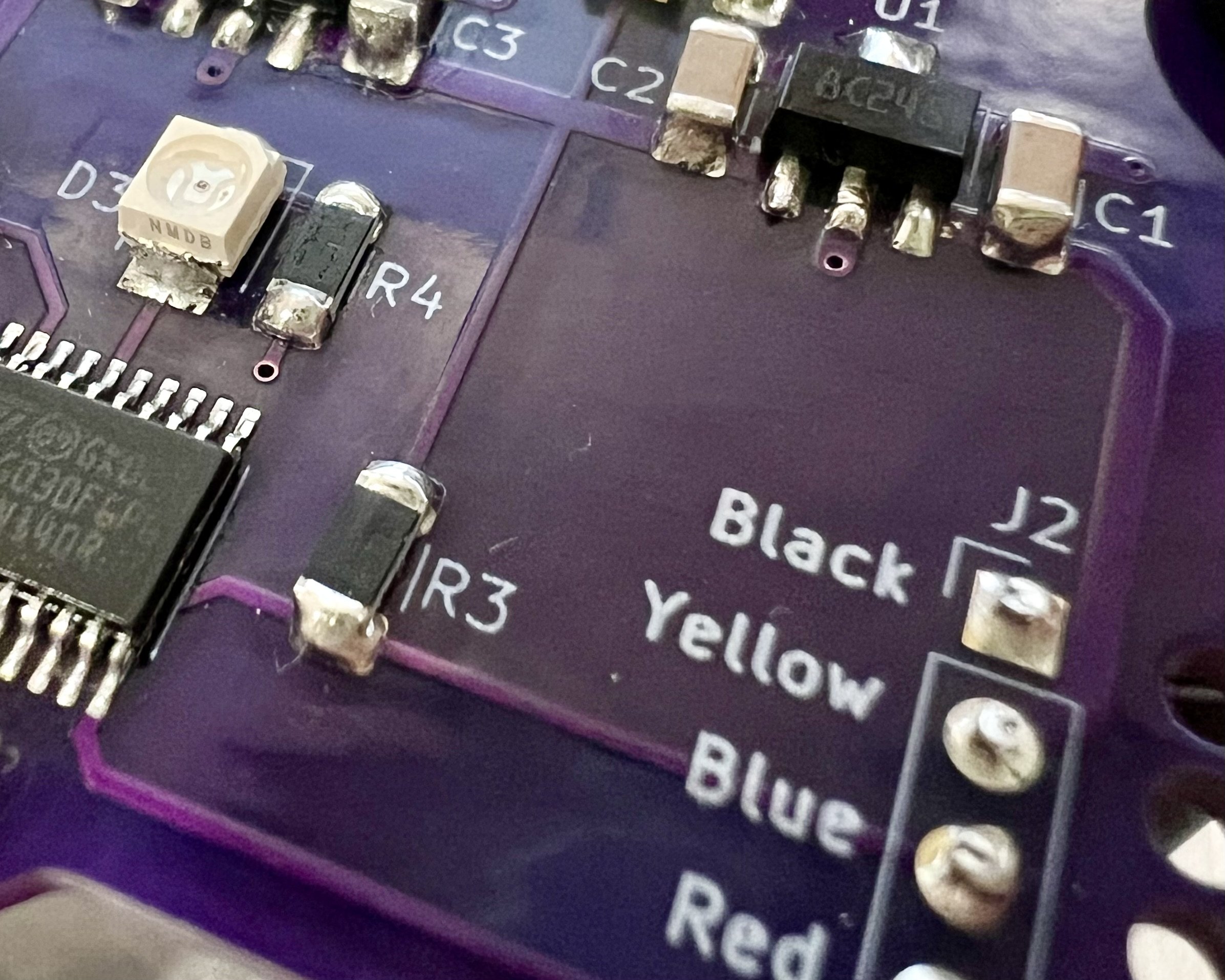
The RX pin needs to be configured to match a similar arrangement on the bike, so we set it up as a Pull-up Input. Our 3.3v STM32 is 5v tolerant, we can get away with using the internal pull-up resistor without any level shifting or further configuration.
    // Grab GPIO A since that's where our USART and LED are.
    let gpioa = stm_dp.GPIOA.split(&mut rcc);

    // Set up the pins to match the circuit board.
    let mut user_led = gpioa.pa11.into_push_pull_output();
    let tx_pin = gpioa.pa2.into_open_drain_output();
    let rx_pin = gpioa.pa3.into_pull_up_input();
With our pins configured correctly, we can move on and set up our peripherals. We identified during reverse-engineering that the signal was 9600 8-N-1, so we can set up our USART to match. A timer is started running, triggering itself every 1/4 of a second.
    // Build our usart, 9600 8-N-1 on USART2 pins.
    let mut usart = stm_dp
        .USART2
        .usart(
            (tx_pin, rx_pin),
            BasicConfig::default()
                .baudrate(Bps(9_600))
                .wordlength_8()
                .parity_none()
                .stopbits(StopBits::STOP1),
            &mut rcc,
        )
        .expect("Failed to initialize USART2.");

    // Use TIMER17 as our Blinky, triggering every 1/4 second.
    let mut timer = stm_dp.TIM17.timer(&mut rcc);
    timer.start(MicroSecond::micros(250_000));
Now we’ve brought up all of our peripherals, we can let the debugger know we’re ready to go.
    // Show the debugger-operator we're alive.
    rprintln!("Hello, world!");
In an infinite, loop 4 times a second, we turn on the LED, write a message to the USART, then turn the LED off again.
    // Forever more...
    loop {
        // Flash the LED while we send our message out of the USART.
        user_led.set_high().ok();
        writeln!(usart, "Blink!\n").expect("Failed to write to USART2.");
        user_led.set_low().ok();

        // Wait for the timer before we go again.
        block!(timer.wait()).ok();
    }
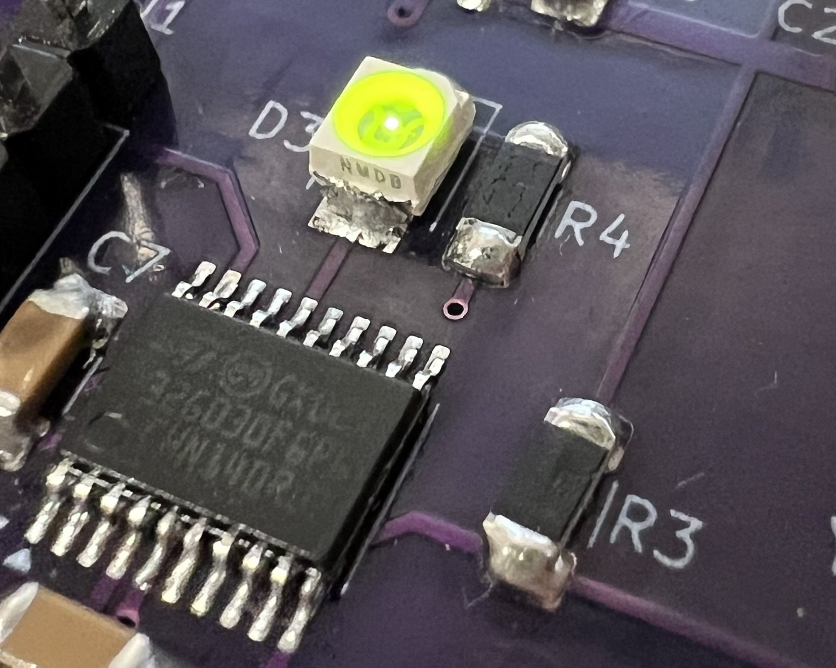
It turns out that it takes so little time to send "Blink!" at 9600 baud that the light flash is barely visible to the naked eye. The following video has been captured at a high frame-rate and played back at 1/8 speed.
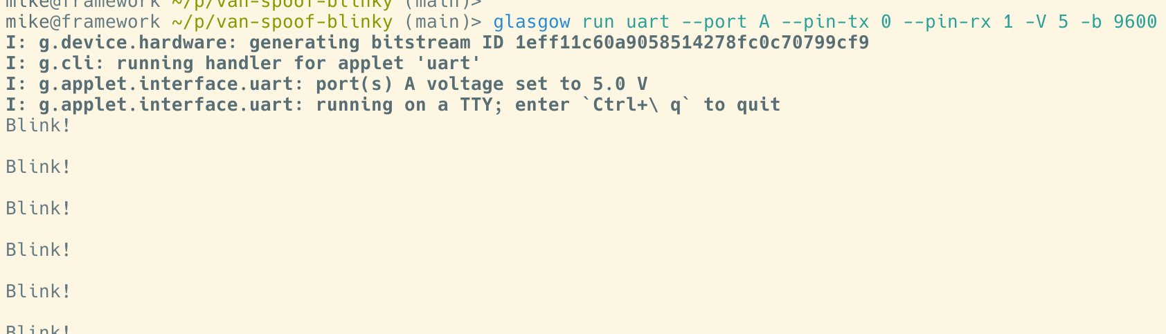
Hooking up a signal analyser like a Glasgow Digital Interface Explorer lets us see the "Blink!" messages scrolling past.
2025-02-14