VanSpoof - Prototype 1 - Hardware
Let's look at building a prototype PCB for my VanSpoof project.
In my first post on reverse engineering the VanMoof e-shifter, I confirmed there was a 24v power supply from the bike to the e-shifter. In the latest reversing post, I determined that the communication is Modbus RTU with its USART lines pulled up to 5v. That won't let me write a fully-featured firmware, but it's more than enough information to let me design a prototype PCB.
I've a few goals I'd like to hit while building this prototype. I really want to get better at soldering SMD components, so I'm going to try to use as few through-hole parts as I can get away with. I'm also interested in designing a board that can be ordered directly from the online PCBA houses, so other folks in need can get their hands on them.
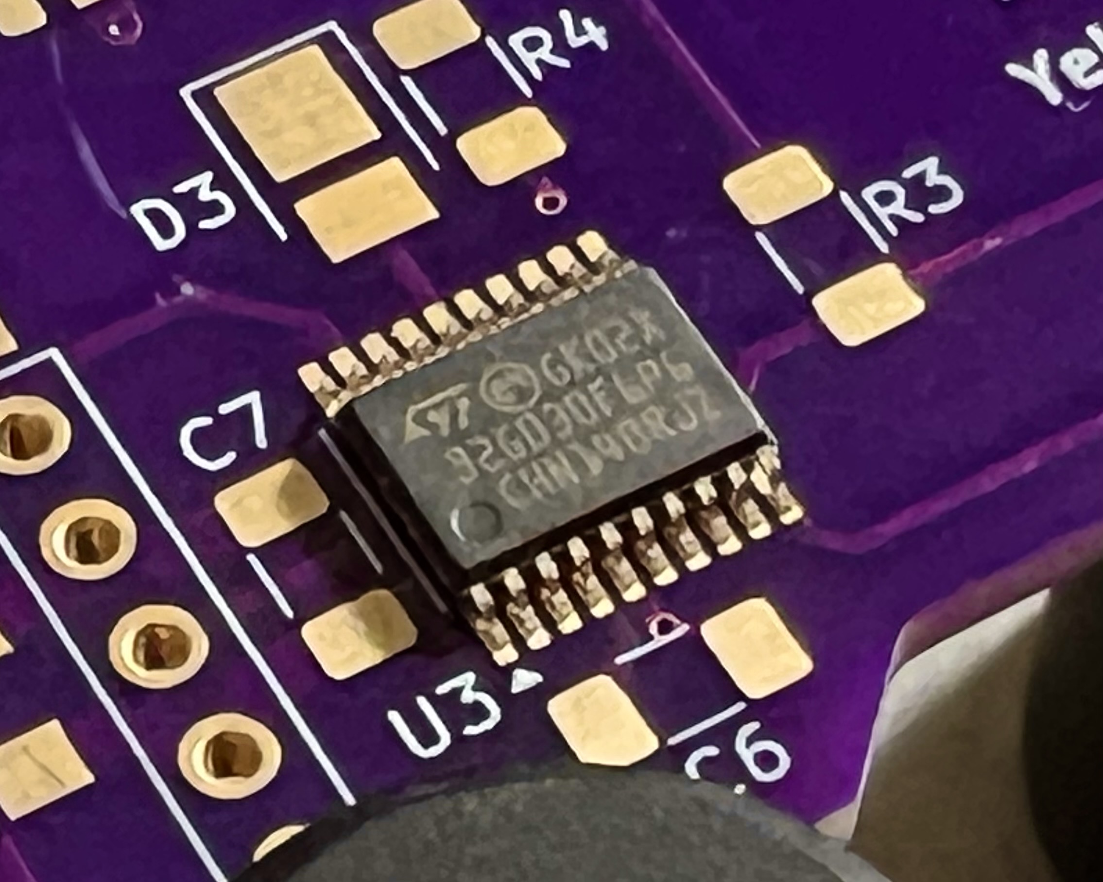
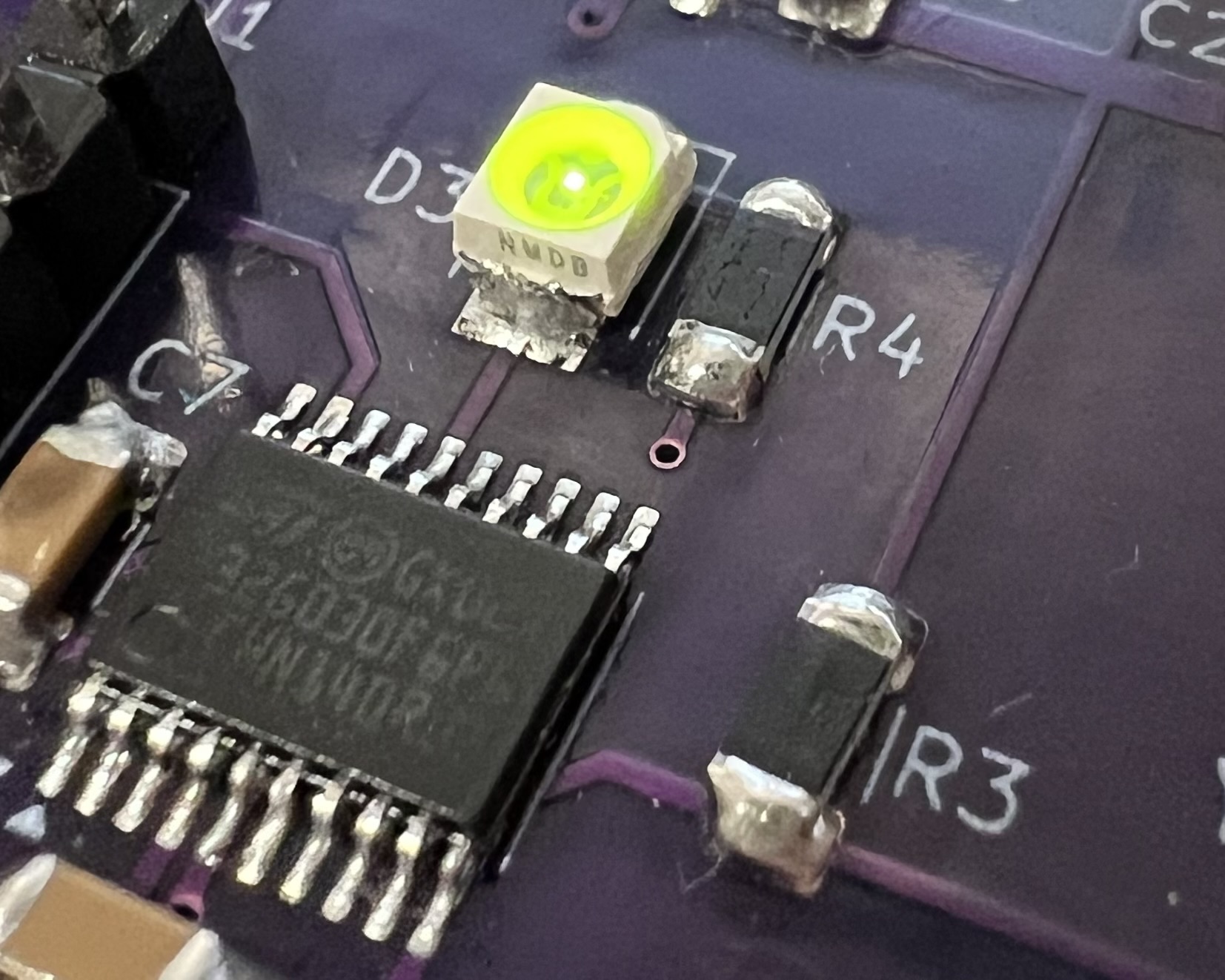
If you've been following this blog for a while, you'd probably be able to guess that I'm looking to use an STM32 as the brains of the spoofer. The catchily named STM32G030F6P6 is a perfect match for my needs. The 20 pin TSSOP footprint is just about hand solderable whilst still providing easy access to each of the peripherals I'll need.
To get everything up and running, the first things to sort out are the power supply subsystems. The 24v supply from the bike needs to be brought down to 5v for the serial pull-ups. A simple linear voltage regulator is good enough for the first round of prototyping. This board is more likely to be running on my workbench than on the bike, so I can simply dial back the input voltage to keep heat dissipation down.
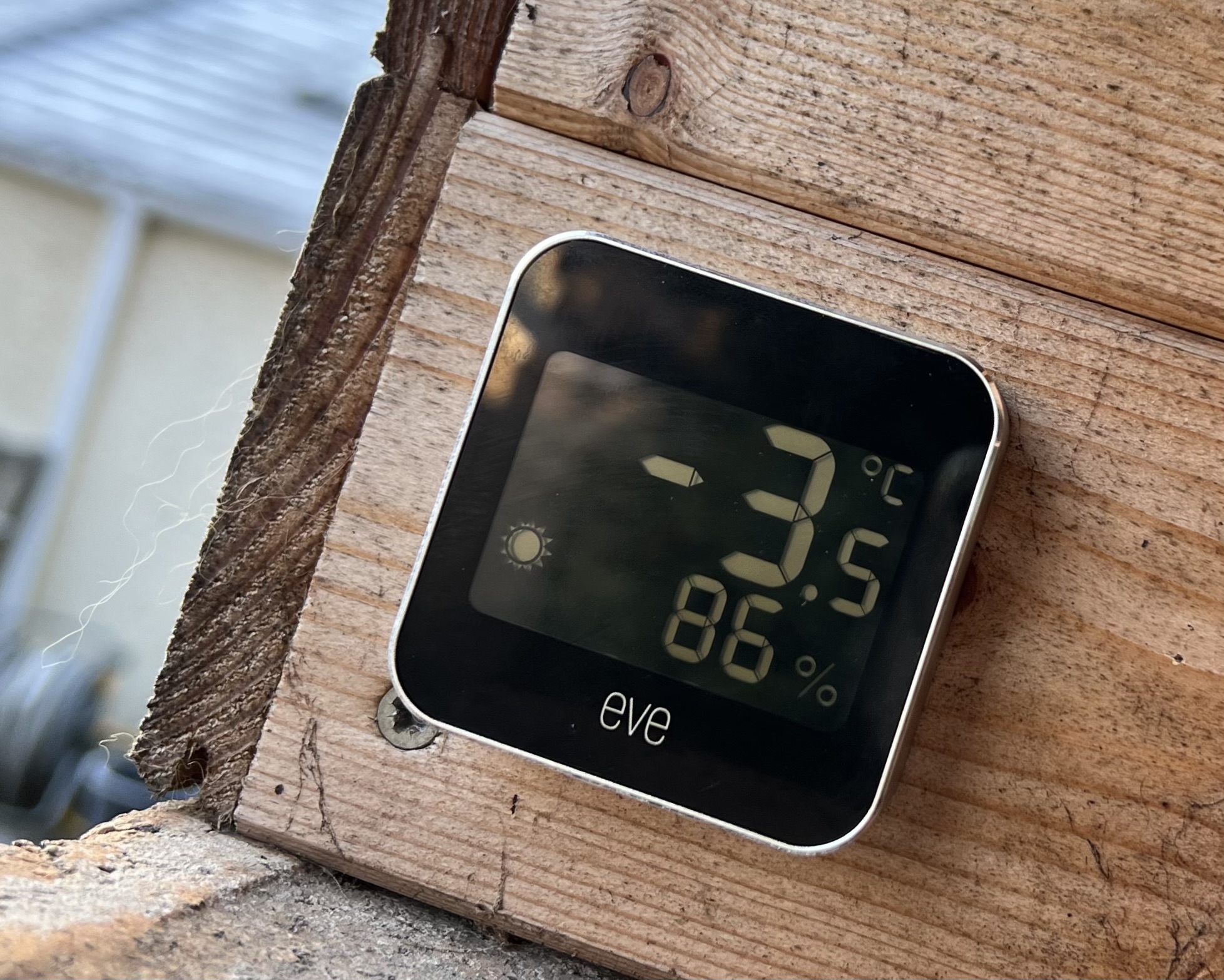
The bike is stored in an outdoor shed all year round, so having parts that are rated to perform at subzero temperatures would be essential to protect the board against those cold winter nights.
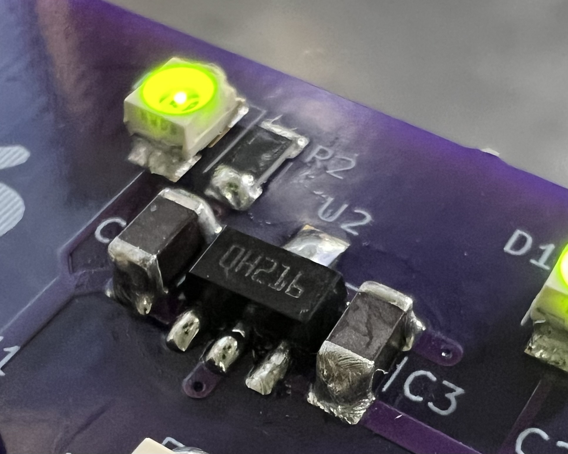
A SOT-89 package device is perfect since it's small enough to keep the board size to a minimum while still being hand solder-able. STMicroelectronics have a chip, the L78L05ABUTR, which meets these criteria.
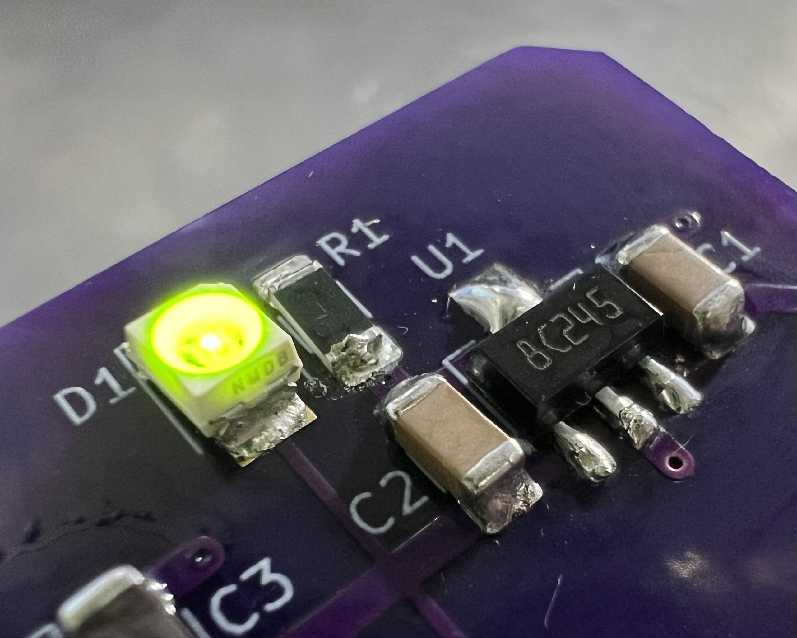
To provide 3.3v from the incoming 5v, a low dropout regulator will be fine. If I can find something that's pin compatible with the 5v regulator, that should keep my board layout coherent. ST's LD2981ABU33TR fits the bill nicely.
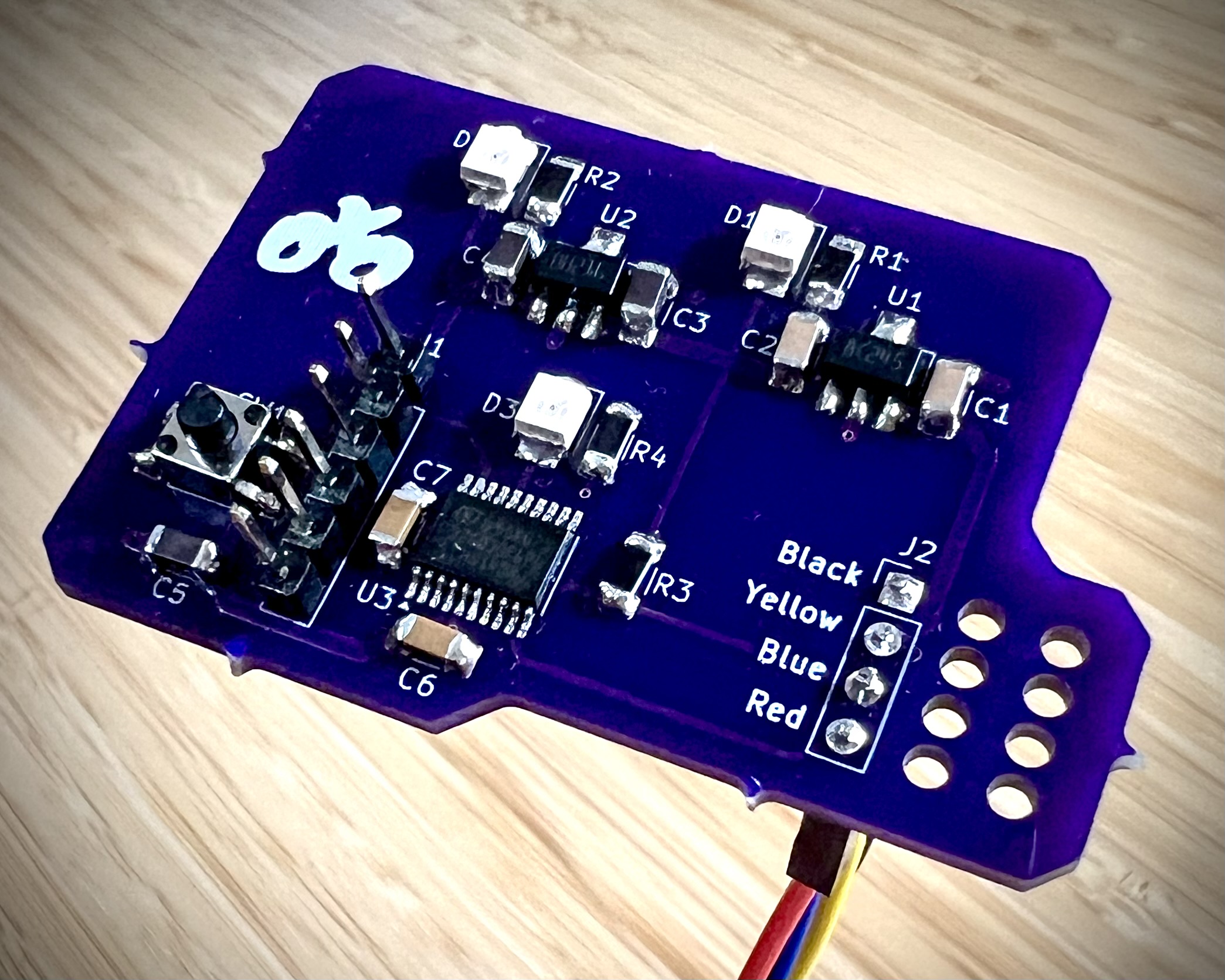
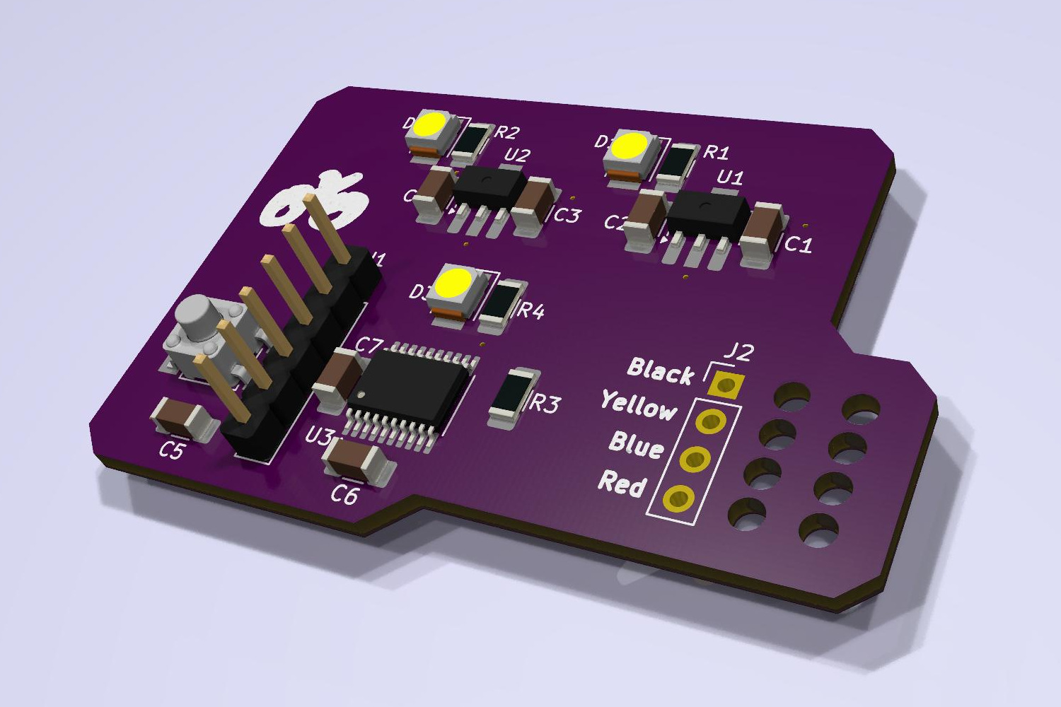
Since the boards will be hand soldered during prototyping, adding status LEDs to the regulator outputs will let me check everything's working as I'd expect.
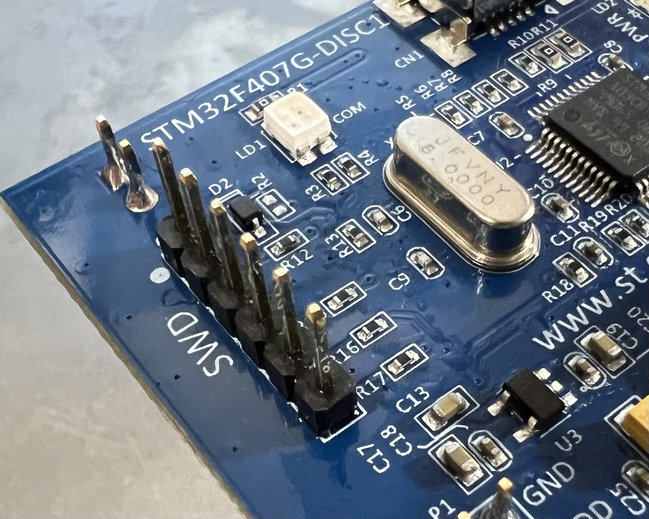
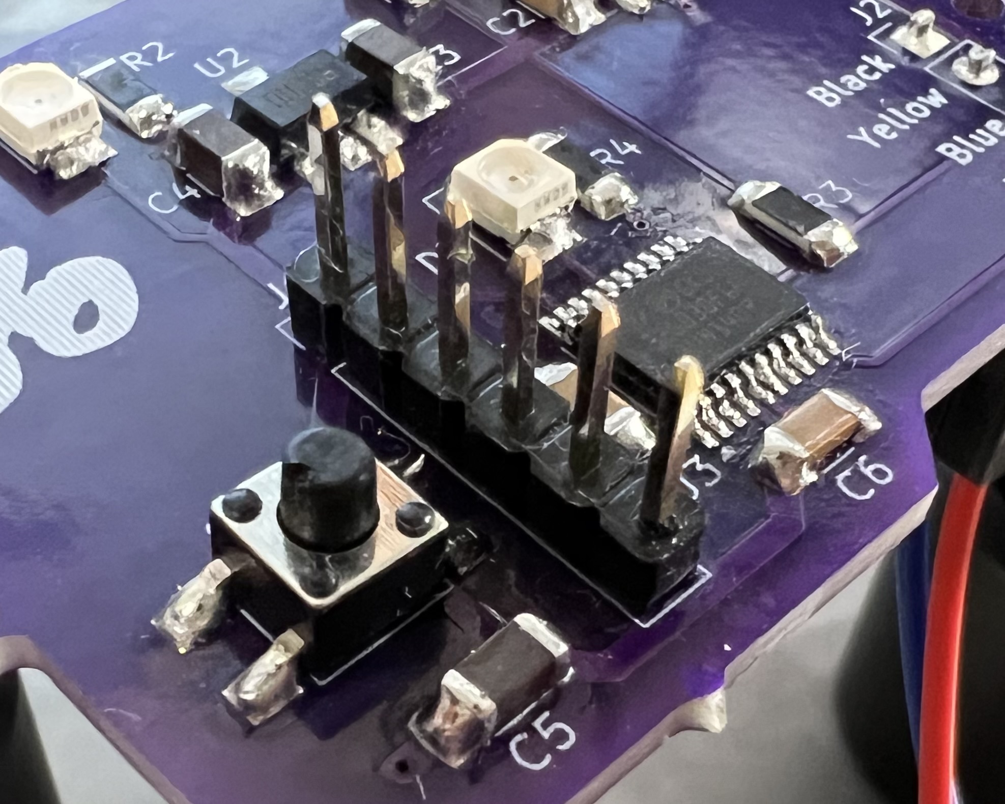
My STM32 Discovery board has an on-board ST-Link which I'll use for programming, so I'll add a matching set of pin headers to my prototype. I'll also include a push-button to reset the microcontroller, just in case I manage to get the firmware in such a state during development that it can't recover itself.
To confirm I've soldered everything together correctly and managed to successfully program the chip, I'll hang an LED off the GPIO for a "blinky" status.
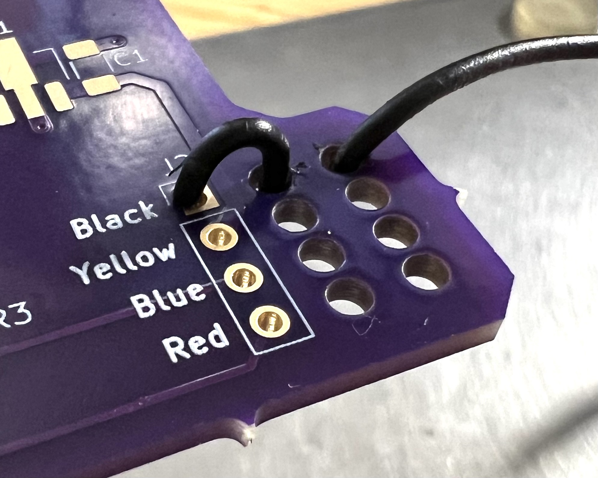
The final physical consideration is for strain relief on the four wires coming in from the bike. The WIGO catalogue specifies the wires attached to the shifter's connector as 30AWG so they'll need careful handling when they're hanging off the side of a bike at 25 kph. A few loops to take up the slack in the wire should keep the solder joint safe.
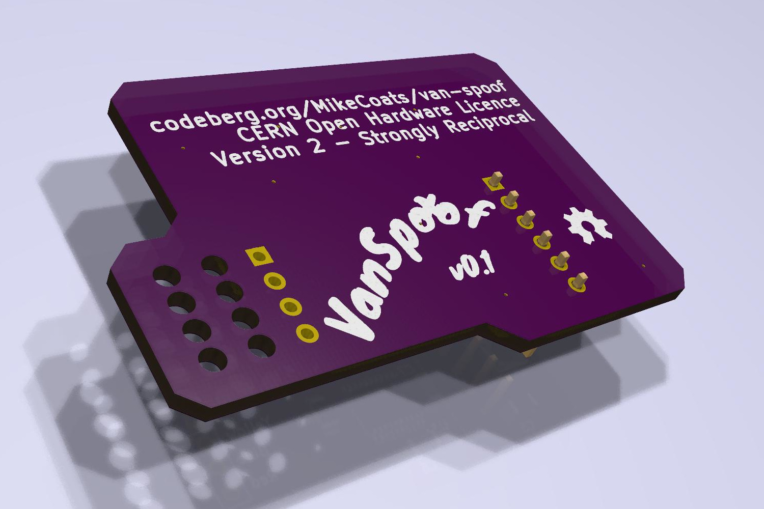
The full schematic and board layout can be found under the prototype-1 tag on my Codeberg repo and is released under the terms of the CERN Open Hardware Licence Version 2 - Strongly Reciprocal.
2025-02-08