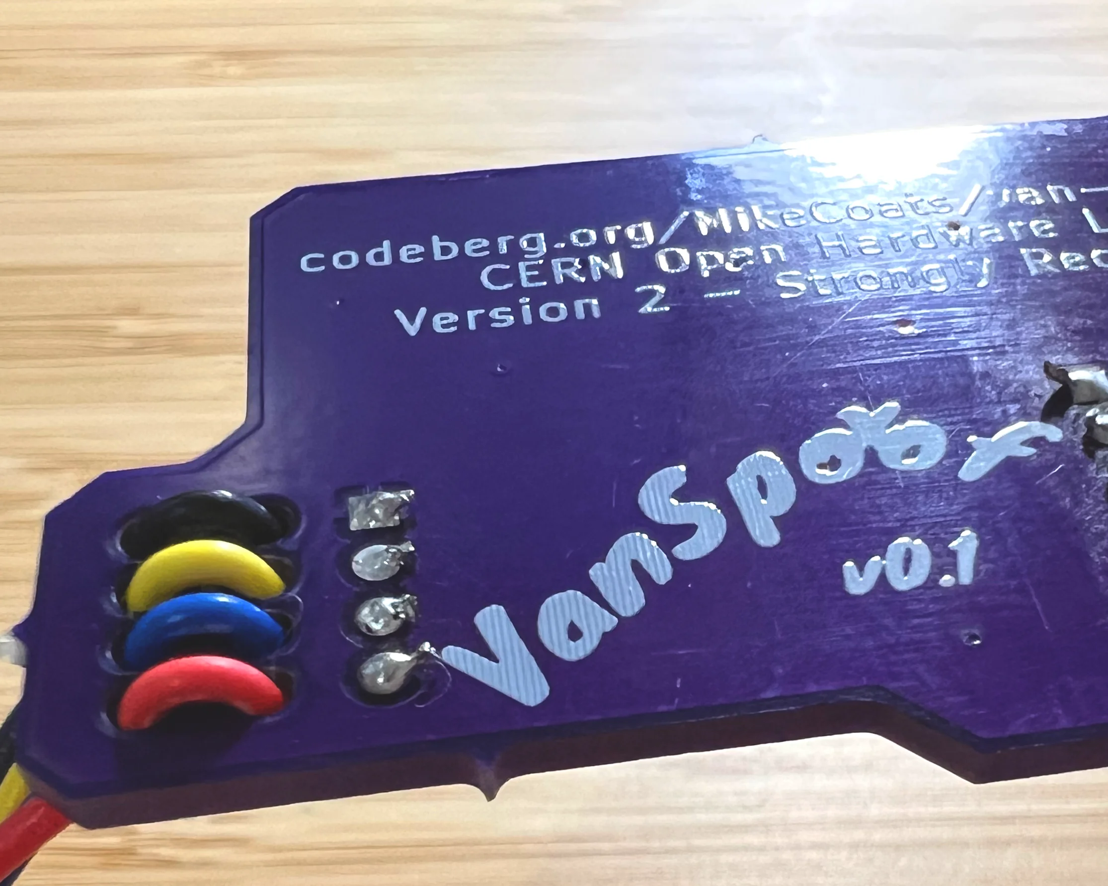
VanSpoof – A-Muntzing We Will Go
With my first few VanSpoof prototypes assembled and the firmware coming together nicely, I realised it was time to start working on the second and hopefully final version of the board.
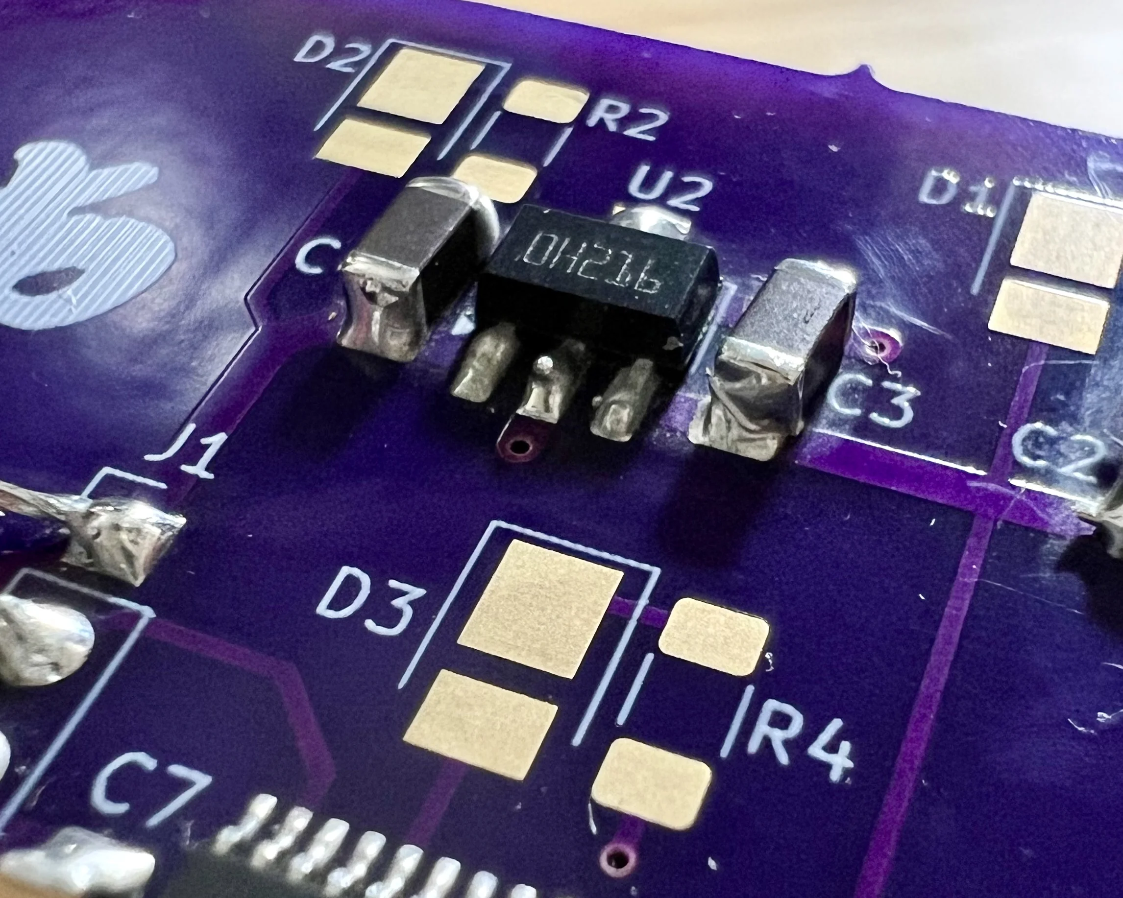
I had noticed that the L78L05, responsible for providing 5 V for the microcontroller's LDO and the USART pull-up resistor, was sometimes getting a little hot.
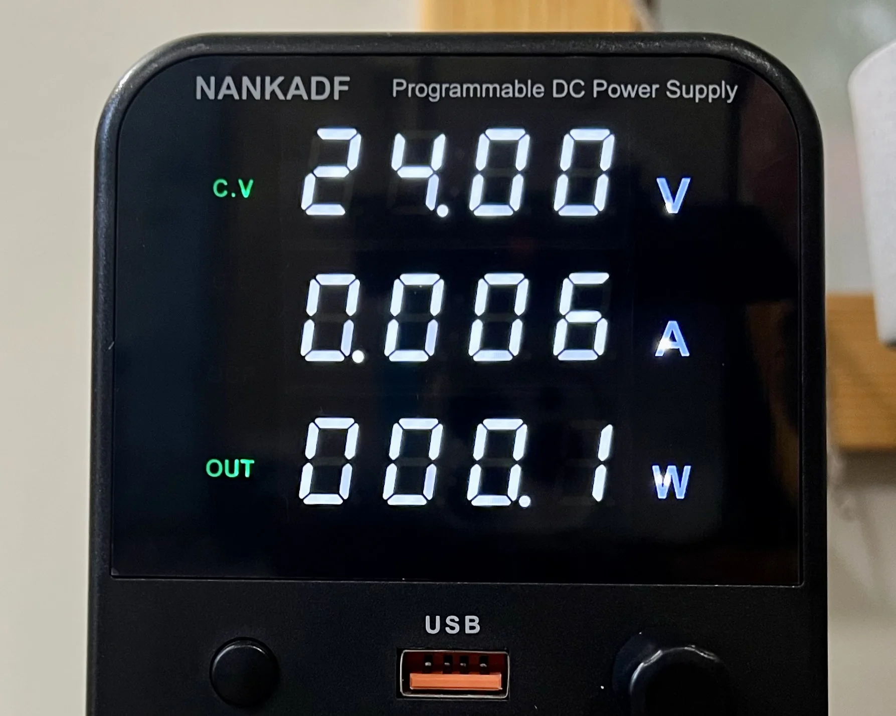
The initial version of the VanSpoof circuit was my first time designing with SMD parts, so I included a bunch of extra LEDs to prove that each stage of the power supply and the microcontroller were working. According to my power supply, at 24 V my circuit is drawing 27 mA and the L78L05 handles about 19 of those 24 V. That's about 0.6 W being dropped by the regulator.
The resistor in this slow-motion video is burning 0.5 W, almost equivalent to the L78L05's load, and provides more than enough heat to flash boil IPA on contact.
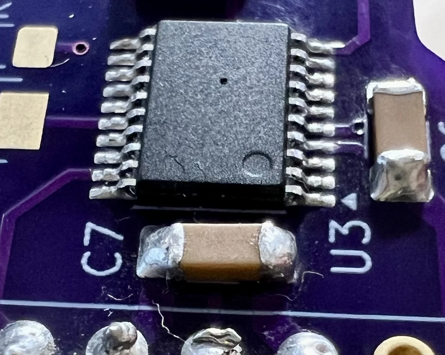
I was intrigued by how much of that current draw was being consumed by my 3 status LEDs and how much was actually being used by the microcontroller to talk to the USART pins. Instead of knuckling down and calculating the values, I turned to the tried and tested method of Muntzing. Unlike the eponymous Mr. Muntz, I didn't physically cut parts out of an existing circuit; I used one of the spare boards I'd ordered from OSH Park, including only the bare minimum of components needed to get the board to boot.
Leaving off those three LEDs and their accompanying resistors dropped the current draw to a maximum of 6 mA. The L78L05 now only has to burn off 0.1 W. It is even running cool enough I don't think I'll need to redesign the power supply circuit for the final version.
In my final design, I also won't be including a physical push button to reset the board, so I removed the whole "External reset circuit" detailed on page 66 of the STM32G030x6/x8 datasheet. The datasheet claims "the reset network protects the device against parasitic resets". I've no formal training in electronics, so I have no idea what that really means or how often you could expect the device to undergo a "parasitic reset". It turns out that my office has the perfect conditions to place an STM32 in to parasitic reset, so every time I booted the board without a debugger connected, it would reset. Adding the NRST capacitor back allowed the board to function properly once more.
Another problem I identified with the first prototype was the pretty slow rise-time on the USART TX signal. Every transition from 0 to 5 V happened with a definite "charging capacitor" shaped curve.
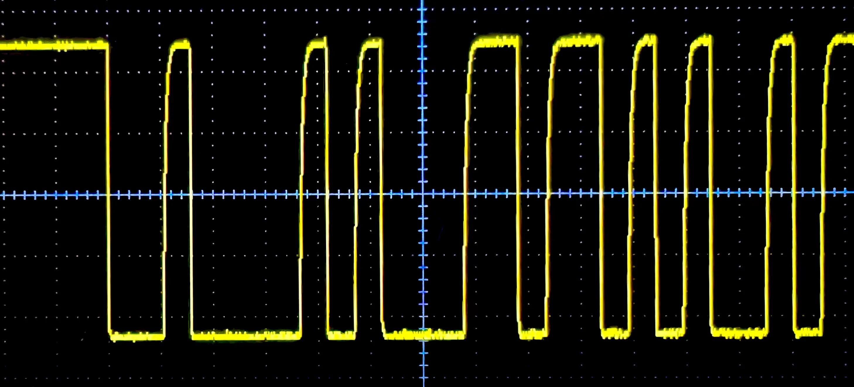
In my original design I used a 62 kΩ resistor as my 5 V pull up, which I picked out of an abundance of caution. The IO pins on these 3.3 V STM32 chips are only 5 V "tolerant", so I didn't want to push too much current through the pin.
According to the datasheet, the chip's internal pull-up resistor has a typical value of 40 kΩ. Using 3.3 V as the supply means that STMicroelectronics would typically push and pull just 82.5 μA through the pin. Being naive, I tried to maintain that low current with my higher 5 V USART signal by staying as close to 60.6 kΩ as I could.
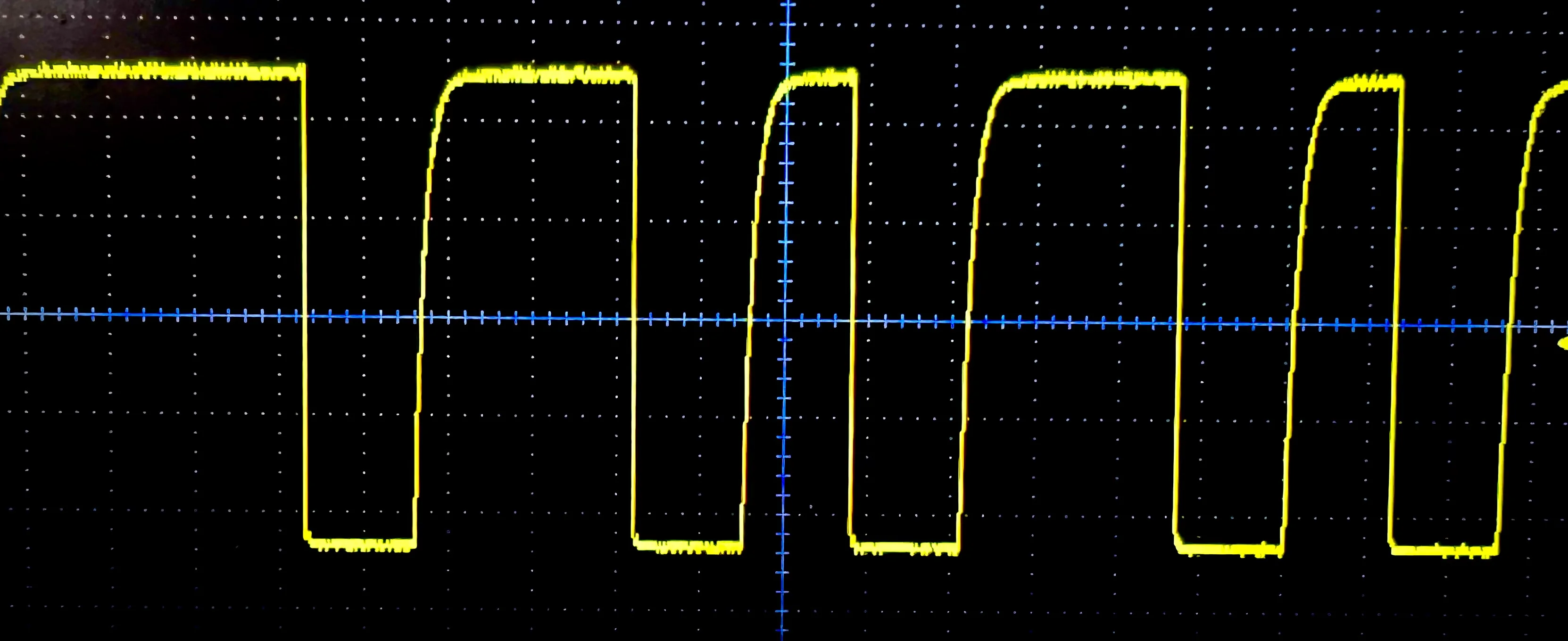
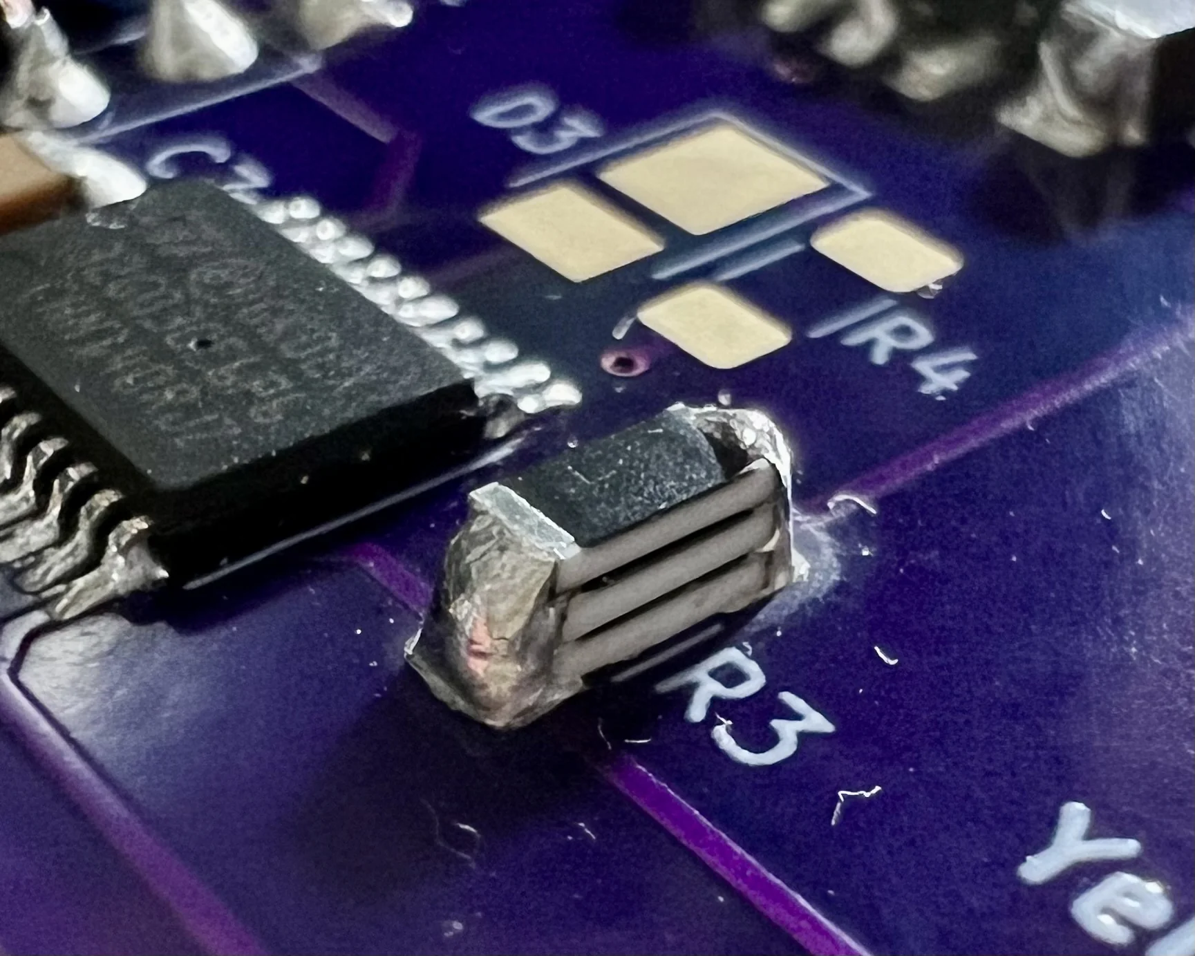
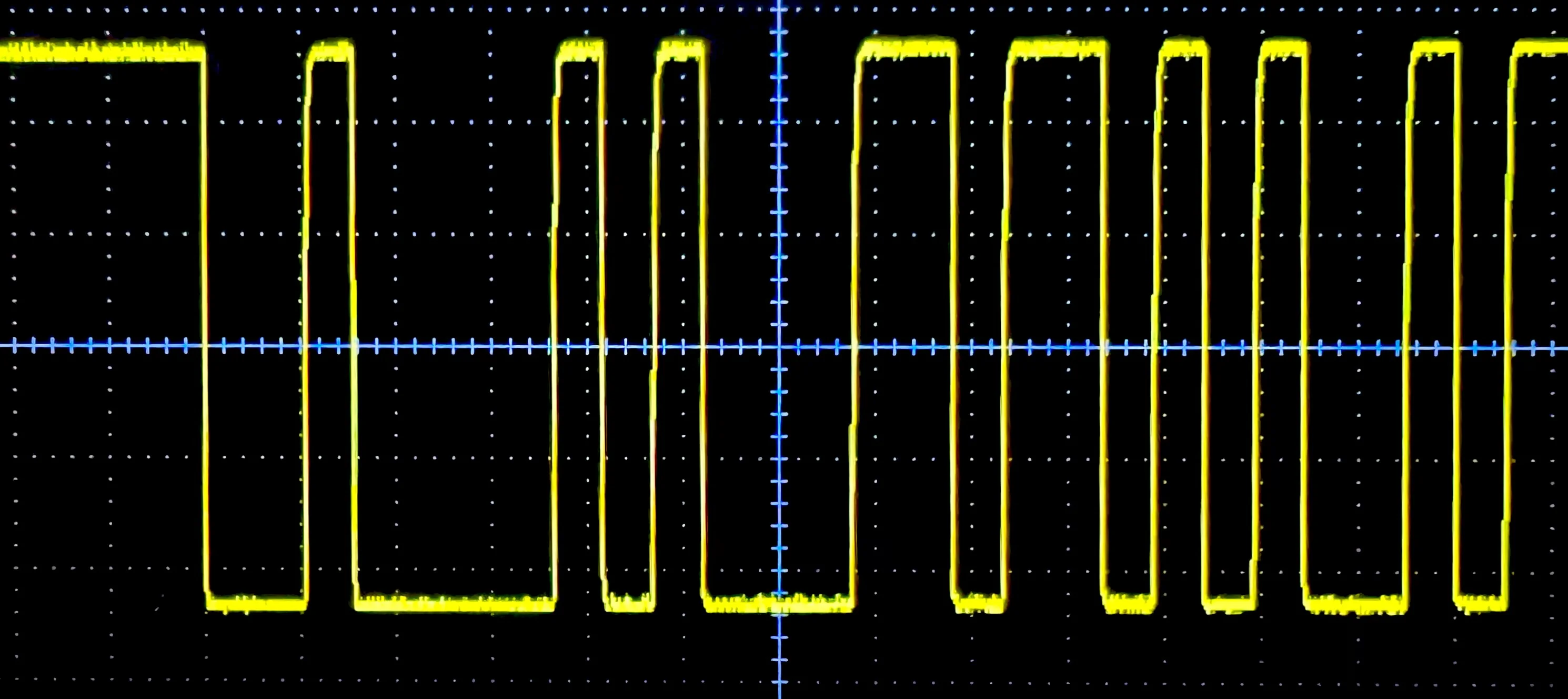
A closer read of the datasheet reveals the IO pins can actually sink and source 15 mA. To quickly assess the response of the board to a lower pull-up value, I stacked three of my 62 kΩ resistors in parallel for an equivalent resistance of approximately 20 kΩ.
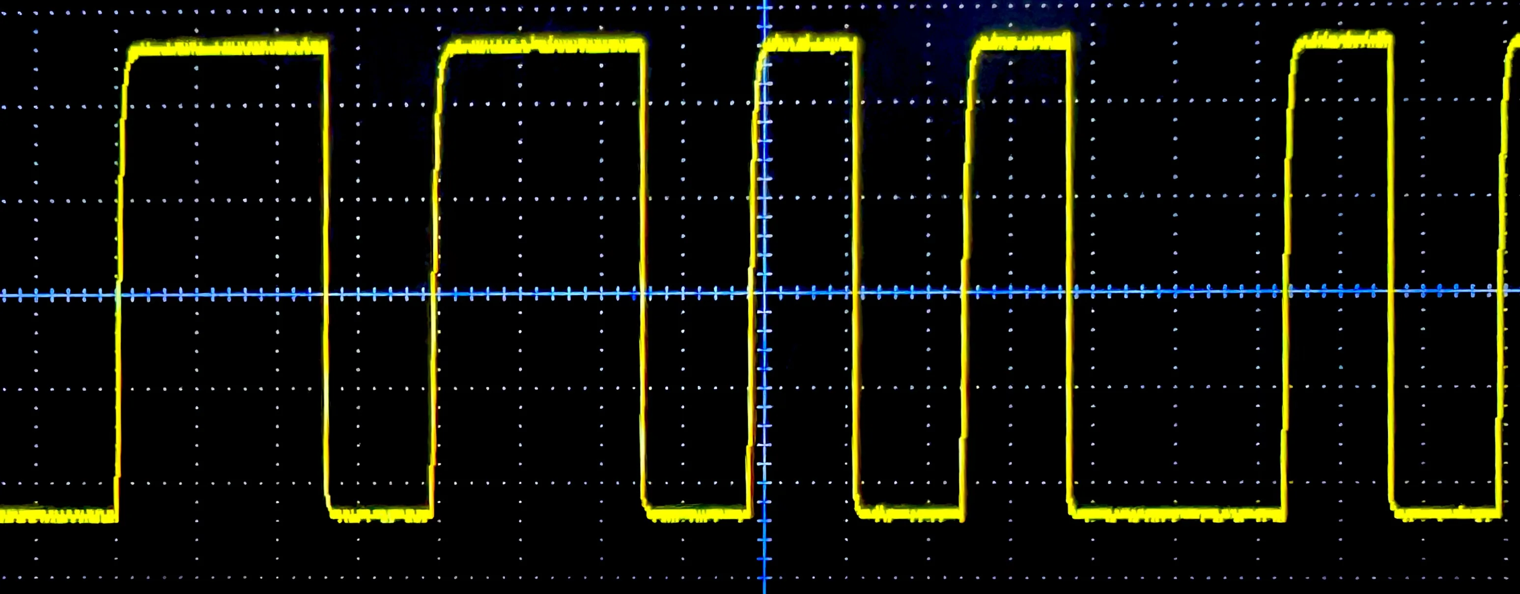
The USART signal's rise-time with this configuration is much better. The new 240 μA current is still two orders of magnitude away from the chip's limits, too.
With these changes tested, I'm much happier designing a new version of the board and sending it off for manufacture.
2025-03-05