STM32 to Blinky with Rust – Part 3 – HAL and Blinky
In the first part of this series, we connected the dev board and installed the probe-rs tool. In part 2, we created a basic project that compiled and built successfully, flashed it to the chip and watched it print “Hello, world!” over the debug interface back to the host computer. This time we’ll blink the LEDs on the STM32F407G-DISC1 Discovery board, starting with a single LED and finishing with all four in a pattern.

As before, you can follow along with the code snippets here, or see the completed single LED blinky project under the naive-blinky tag in my repo. The first thing we need to do is add the STM32 HAL to our Cargo.toml file. This provides all the interfaces we need to access the hardware features of our STM32F4. To specify the unique set of hardware that makes up the STM32F407, we opt in to the F4 runtime feature and the F407 feature.
[dependencies]
# ...
hal = { package = "stm32-hal2", version = "1.8.3", features = ["f407", "f4rt"] }
In the main.rs file, we always need to import the cortex_m package in some fashion to ensure the linker can find a critical-section but, whereas we previously threw away the import, this time we want to pull out Delay so we can use it later to pause between each blink.
- use cortex_m as _;
+ use cortex_m::delay::Delay;
We import Clocks from our renamed stm32-hal2stm32-blinky-rust-part-2-debug/ package which will be used later to configure the pause between blinks, and several parts of the gpio module to allow us to toggle the onboard LEDs.
use hal::{
    clocks::Clocks,
    gpio::{Pin, PinMode, Port},
};
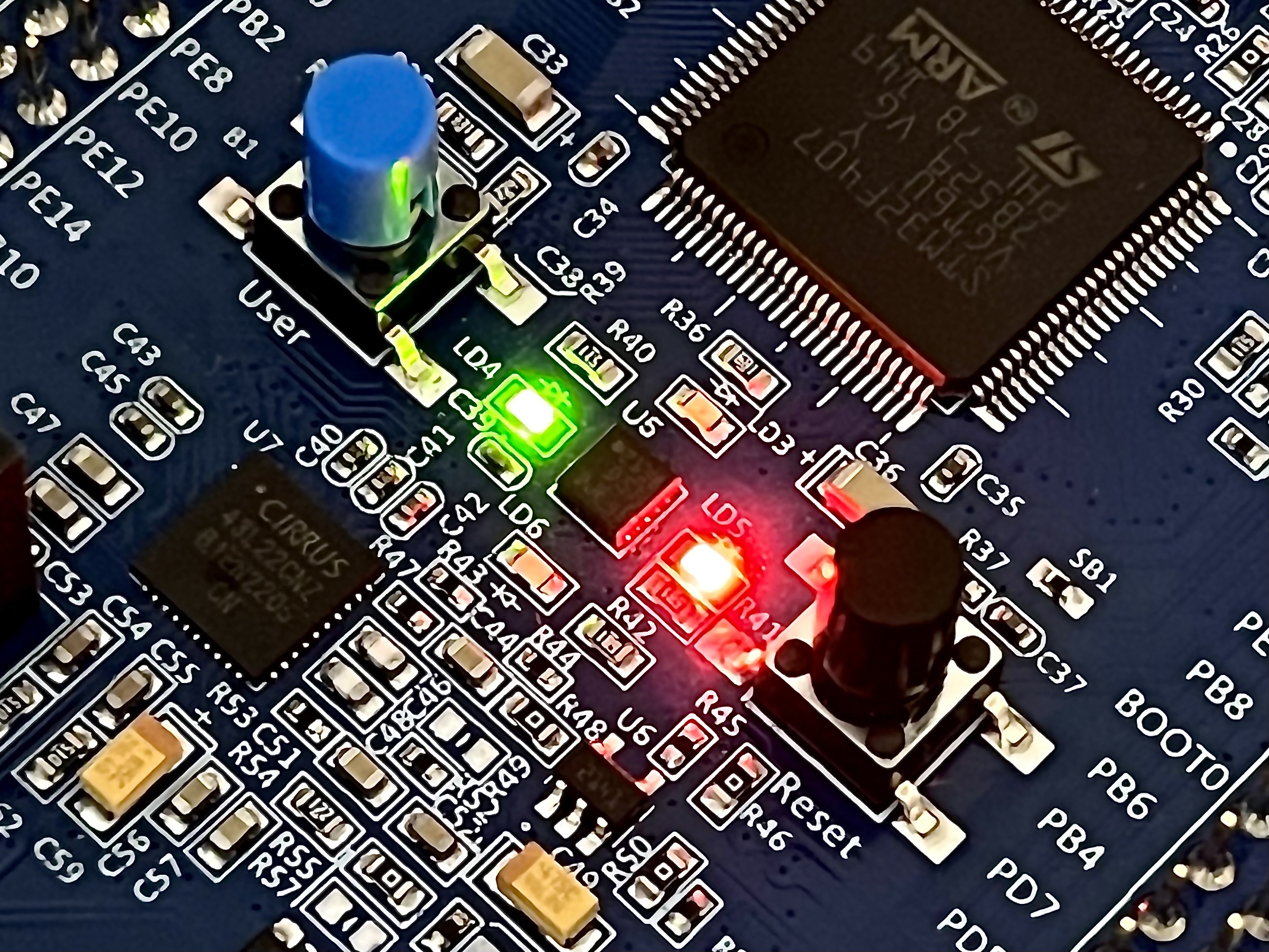
To work out which pins on the chip are connected to which LEDs on the board, we can refer to the Discovery board’s user manual.

The orange LED, labelled LD3 on the board, is connected to PD13 on the chip, so we set it up as an output pin.
let mut north_led = Pin::new(Port::D, 13, PinMode::Output);
We then set up the MCU’s clock configuration, to be used later when we pause between blinks.
let clock_cfg = Clocks::default();
clock_cfg.setup().unwrap();
let mut delay = Delay::new(
    cortex_m::Peripherals::take().unwrap().SYST,
    clock_cfg.systick(),
);
Now we’ve prepared the LED’s pin for toggling on and off and a delay timer that can be used to pause between blinks, we can do just that. In a loop. Forever!
loop {
    north_led.toggle();
    delay.delay_ms(1_000);
}
At this point cargo run will be compile and flash the above code to the STM32, and one of the LEDs will flash slowly.
That’s cool, but if you’re reading this blog post and have followed along so far, there’s a chance you’re a massive nerd, just like me. Given 4 LEDs, we could flash a pattern such as displaying the binary numbers from 0 to 15 but that would be too easy. Instead we can flash the Gray coded pattern of those numbers instead. The completed code for this stage can be found under the gray-blinky tag in my repo.
First we need to create an array with all 16 possible iterations of a 4-bit Gray code. We then need a similarly sized 4-bit bitmask to represent each LED.
const GRAY: [u32; 16] = [
    0b0000,
    0b0001, // Least-significant bit 0 appears first
    0b0011, // LSb 1 appears second
    0b0010,
    0b0110, // LSb 2 appears third
    0b0111,
    0b0101,
    0b0100,
    0b1100, // LSb 3, or MSb, appears fourth
    0b1101,
    0b1111,
    0b1110,
    0b1010,
    0b1011,
    0b1001,
    0b1000,
];

const NORTH: u32 = 0b0001;
const EAST: u32 = 0b0010;
const SOUTH: u32 = 0b0100;
const WEST: u32 = 0b1000;
If we perform a bitwise AND between a position in the Gray array and one of those cardinal directions’ bitmasks, we’ll be left with a positive value indicating when that LED should be illuminated. We can then make the same test for the other three directions and we’ll know whether to light each of our LEDs on every cycle through the loop.
let mut counter: usize = 0;
loop {
    let bits = GRAY[counter];

    if bits & NORTH > 0 {
        north_led.set_high();
    } else {
        north_led.set_low();
    }
    // ...
}
At the end of every loop we need to increment our position in the Gray list, but we must not overflow the end of the array and instead jump back to the start.
loop {
    // ...
    counter += 1;
    if counter > 15 {
        counter = 0
    }
}
Compiling and flashing the board with these changes will make the LEDs on the board flash according to the current position in the Gray code array.
There we go! STM32 to Blinky with Rust complete. We can now use this project as a worked example to base any other STM32 embedded Rust projects from and give them a hopefully head-ache free kickstart.
2024-07-04