Using a Spy! Break! Inject! to Sniff I2C Traffic
I've been exchanging emails, discussing debugging protocols like I2C with my Spy! Break! Inject! and I thought that writing this process up as a blog post might be useful to others.
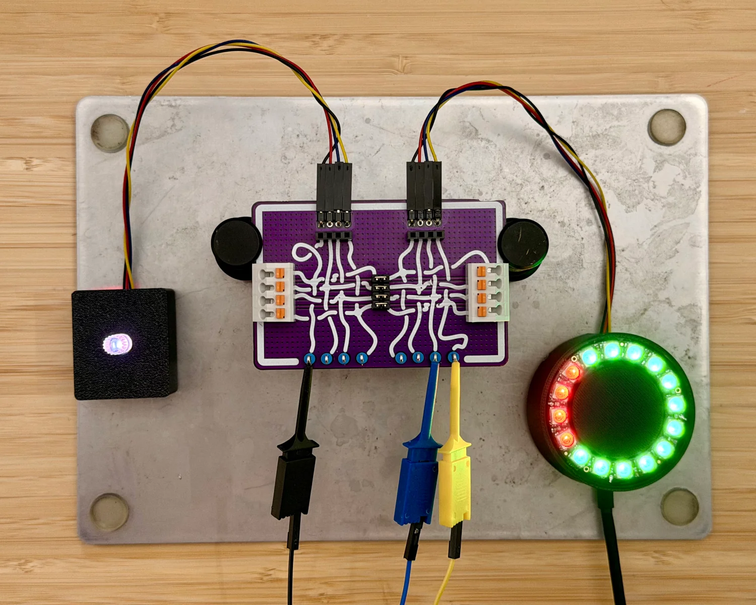
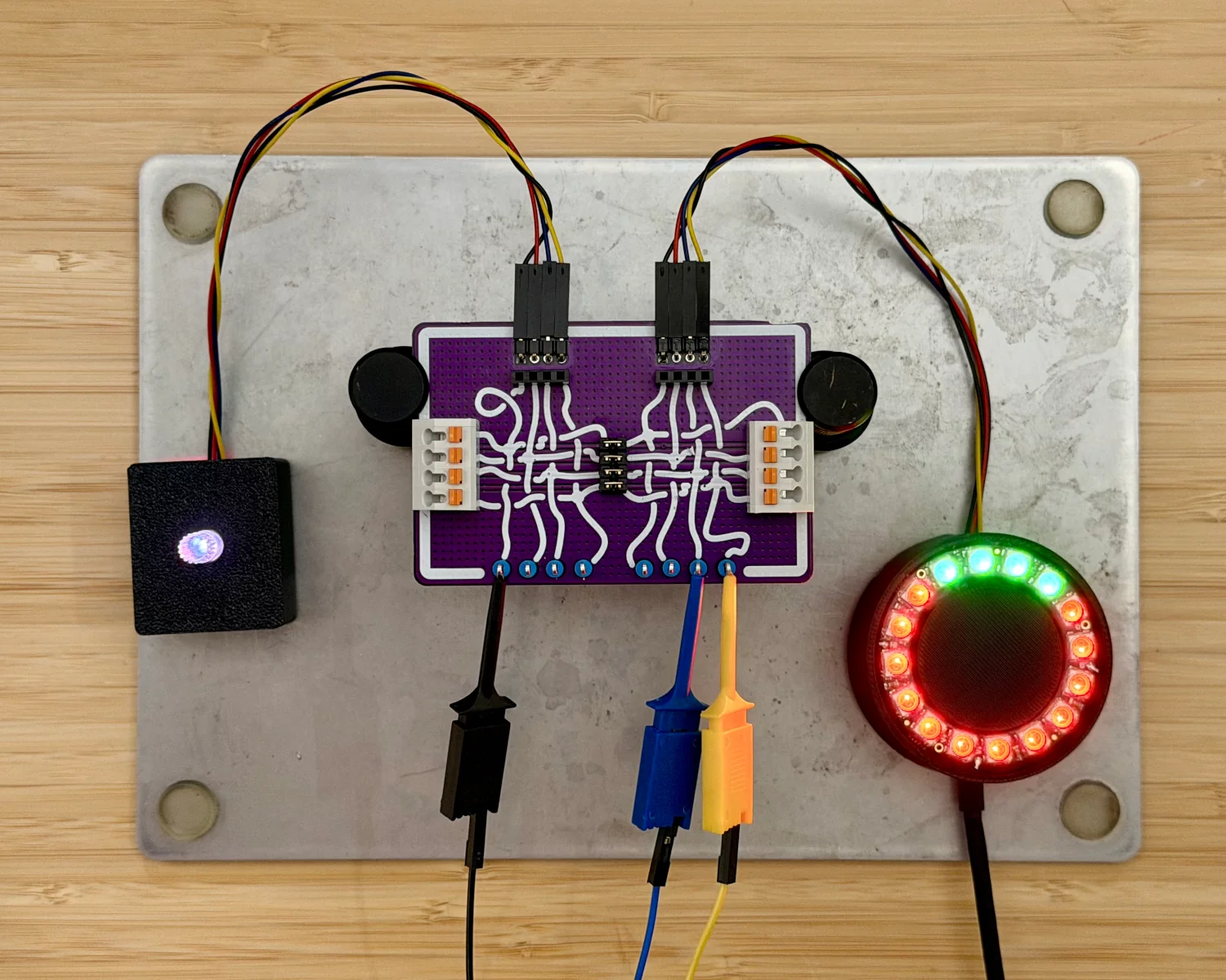
I've built up a mystery project, for our worked example, that comprises a remote-control rotary encoder and a ring of LEDs as an output display. They are connected via a four-wire cable that looks suspiciously like the I2C-based Qwiic.
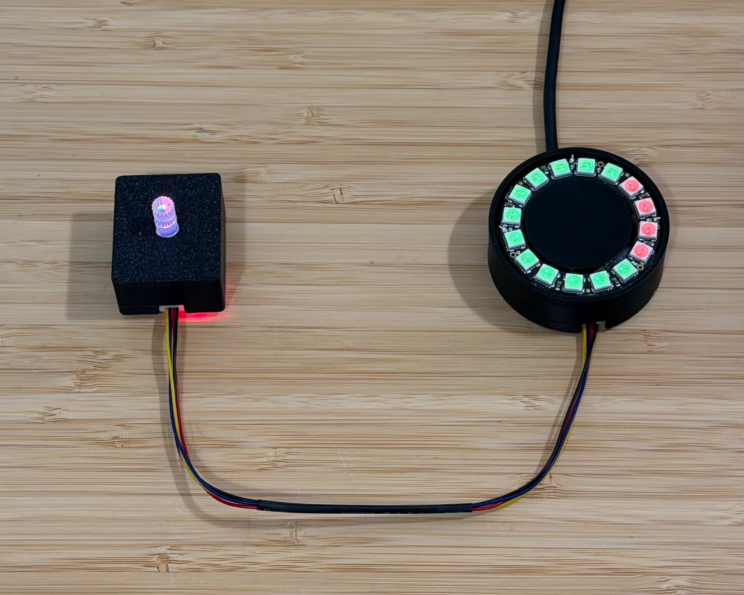
As can be seen in the video, turning the knob notch by notch causes the LEDs to turn from red to green one by one.
To begin our reverse engineering process, we first need to insert our Spy! Break! Inject! in the path of the communication. With our new setup in place, we can observe that we've not killed or damaged anything and communication is still flowing correctly.
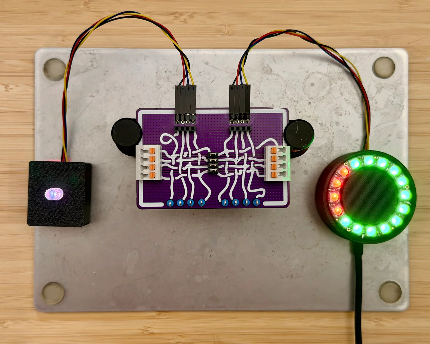
With the various inputs and outputs of the Spy! Break! Inject! available to us, we can now begin probing the signals on each of the wires.
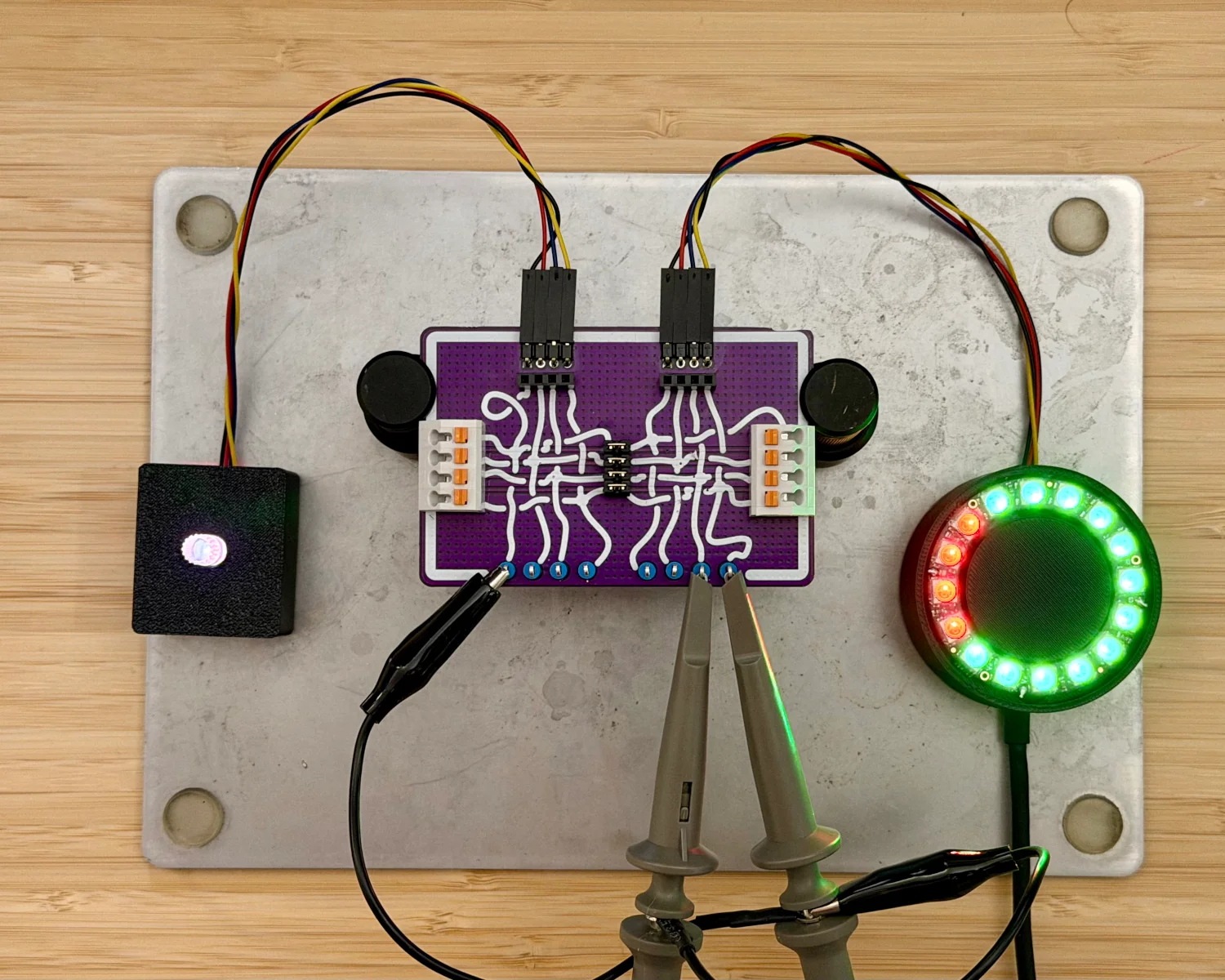
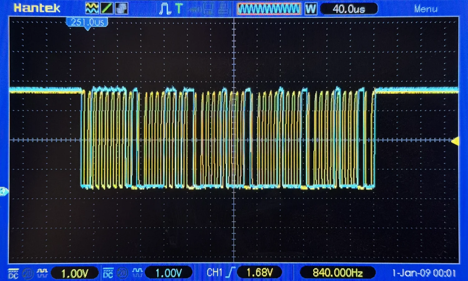
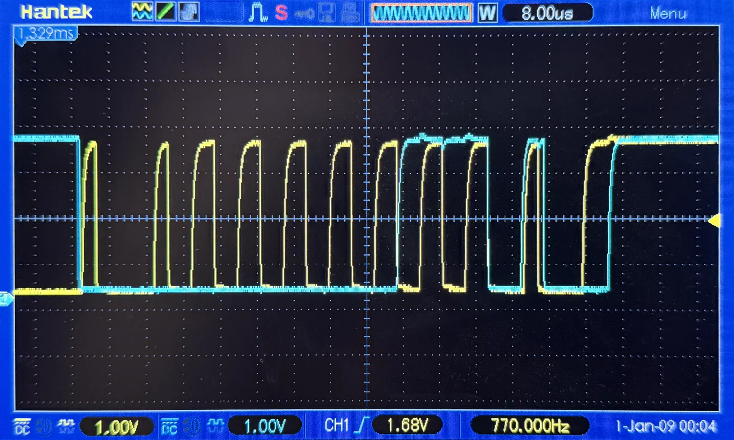
It doesn't take long to determine the black wire is ground, the red is 3.3 volts, and there appears to be some sort of open-collector/pull-up arrangement on the yellow and blue wires. Looking at the traces on the oscilloscope, we can see that the yellow wire appears to be the clock signal with the blue wire as the corresponding data signal.
Now we've confirmed the rough "shape" of the signals, we can hook up a digital logic analyser to capture and analyse them.
If you start digging into the sigrok documentation, you'll find a whole host of analysers based around the FX2 chips. Going on a wee trawl of eBay, Amazon, and similar sites will reveal a slew of compatible original models and cheap imitation copies. One I've used and I'm happy with is the nanoDLA v1.3 from MuseLab. It's inexpensive, comes pre-packed with little clip-on probes for immediate use, and has a USB-C port for easy connection. You can grab it directly from them on Tindie or through their AliExpress storefront.
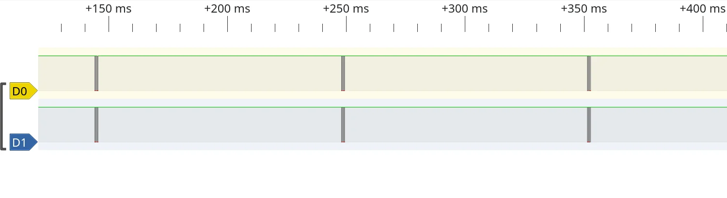
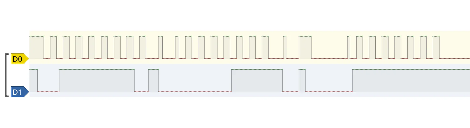
Capturing the signals in sigrok's PulseView, we can see the clock and data lines are held high for the majority of the time, with a small flurry of highs and lows every 100 ms. We can again see, the yellow signal is definitely clock "shaped" with data being transmitted on the blue wire.
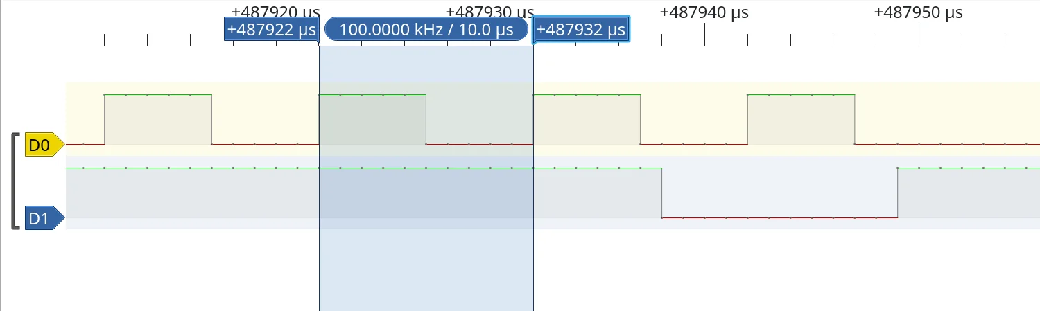
Zooming all the way in and using PulseView's measuring tools, we can see the clock signal is pretty much bang on 100 kHz.
A quick web search for open-collector clock-signals running at 100 kHz all but confirms we're looking at an I2C signal. We can now set the logic analyser running as we twist and turn the knob, observing the change in the transmitted data.
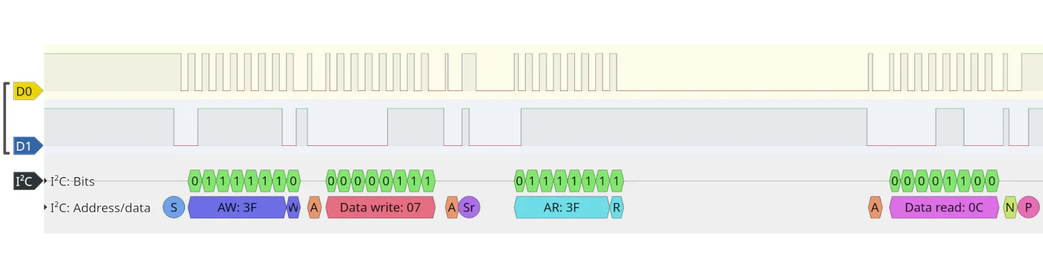
With an I2C protocol decoder added to the analyser view, we can see the I2C controller sends a 0x07 signal to the device at 0x3F, followed by a request to read data back from the 0x3F device. The data returned is 0x0C, which translated to decimal is 12, matching the number of LEDs currently illuminated green on the display.
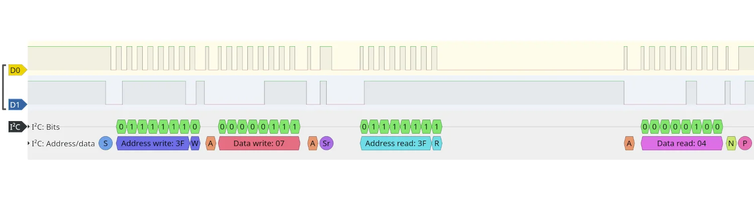
Twisting the controller to show only four green LEDs, we see the same 0x07 being written to 0x3F, but this time the data returned is 0x04. This, unsurprisingly, is also four in decimal, corresponding to the number of LEDs illuminated on the display.
Ta da! We've successfully inserted ourselves in the path of the I2C traffic between the controller and the display, with our Spy! Break! Inject!, then captured, decoded, and interpreted the messages.
This is enough to get us started on reverse engineering our own devices, but there are more features of the Spy! Break! Inject! that can be used to further investigate the communication. If you go back to the oscilloscope, you can start removing the jumpers on the board. Probing either side of the broken connection will allow you to determine whether it's the I2C controller or target that's responsible for the pull-up resistors on the yellow and blue wires.
This sort of information becomes critical when you're trying to reverse-engineer a product not just to understand it, but to build a replacement.
2026-01-31