Back 2 Basics - R-2R Ladder DAC
As is plainly clear from my efforts during the design of the VanSpoof boards, particularly in my earlier "Muntzing" post, I am not a trained professional when it comes to electronics. I even say as much during my OSHWA Summit talk, where I described myself as an "enthusiastic amateur". I'd like to remedy that as much as possible, so I'm going to build a series of "back to basics" projects. These will get me building real, practical, circuits that prove that concepts learned from books, blogs and videos can be translated into physical objects. I'm not talking about showing V=IR & P=VI or LEDs and resistors, but projects like op-amp buffers, active filters, and, today's topic, R-2R Ladder DACs.
An R-2R Ladder DAC is an arrangement of resistors that translates an n-bit binary representation of a number to an analogue value between 0 and almost V+.
In my parts bin I happen to have several strips of 10 identical resistors, which is just enough to build a 3-bit DAC. This is the schematic, simplified for analysis in LTSpice.
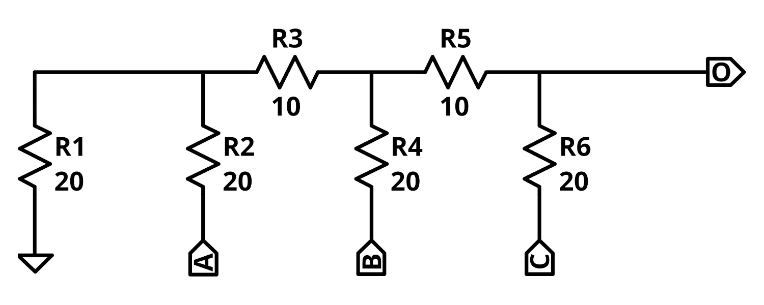
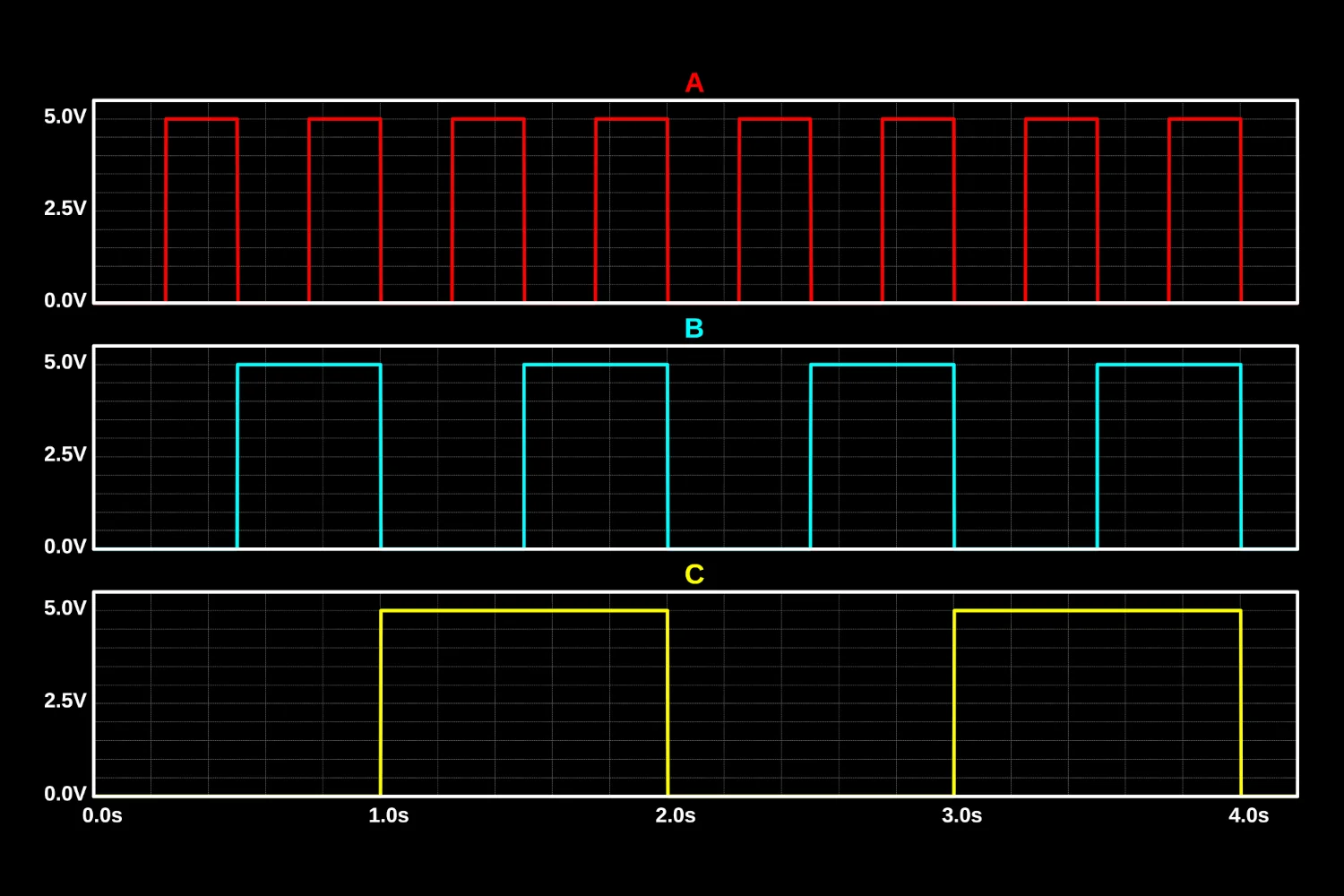
In LTSpice we apply voltages to toggle the A pin with the LSB (the 1's column), the B pin as the middle bit (the 10's place), and the C pin as the MSB (the 100's digit).
Combining these bits using the R-2R Ladder DAC, we see a ramp from 0 through to 7. What's interesting is that we see spikes during the 1 to 2, 3 to 4, and 5 to 6 transitions.
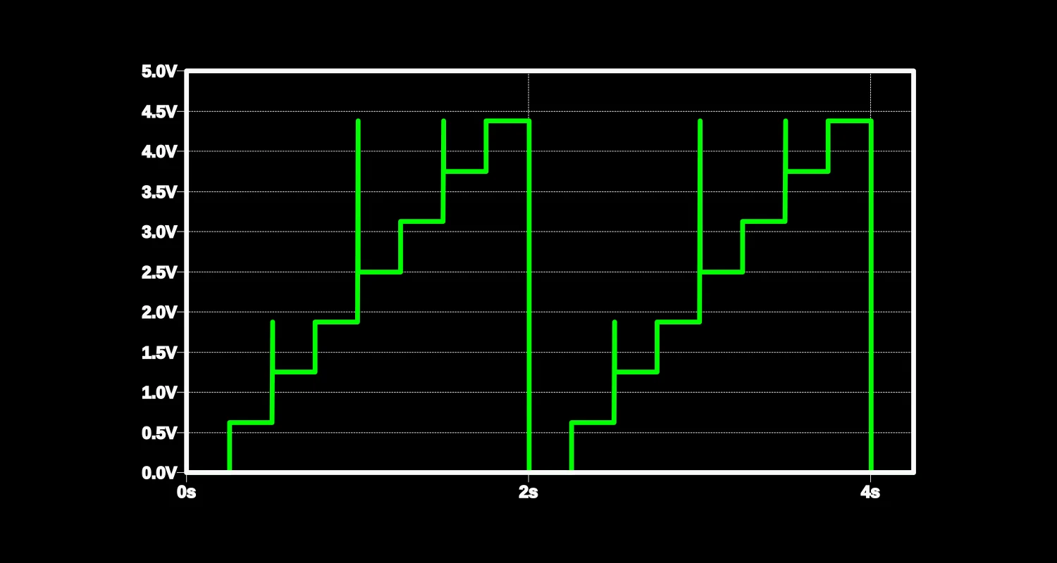
These coincide with more than one bit changing at a time.
During the transition between 1 and 2, or 01 and 10, we might pass through 00 and 11 depending on which bits turn on or off first.
These "intermediate" states are the reason Gray codes exist, as discussed in my earlier "Blinky" post and firmware.
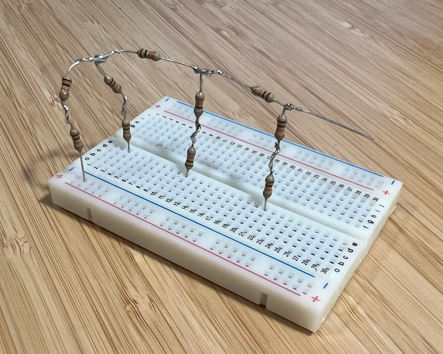
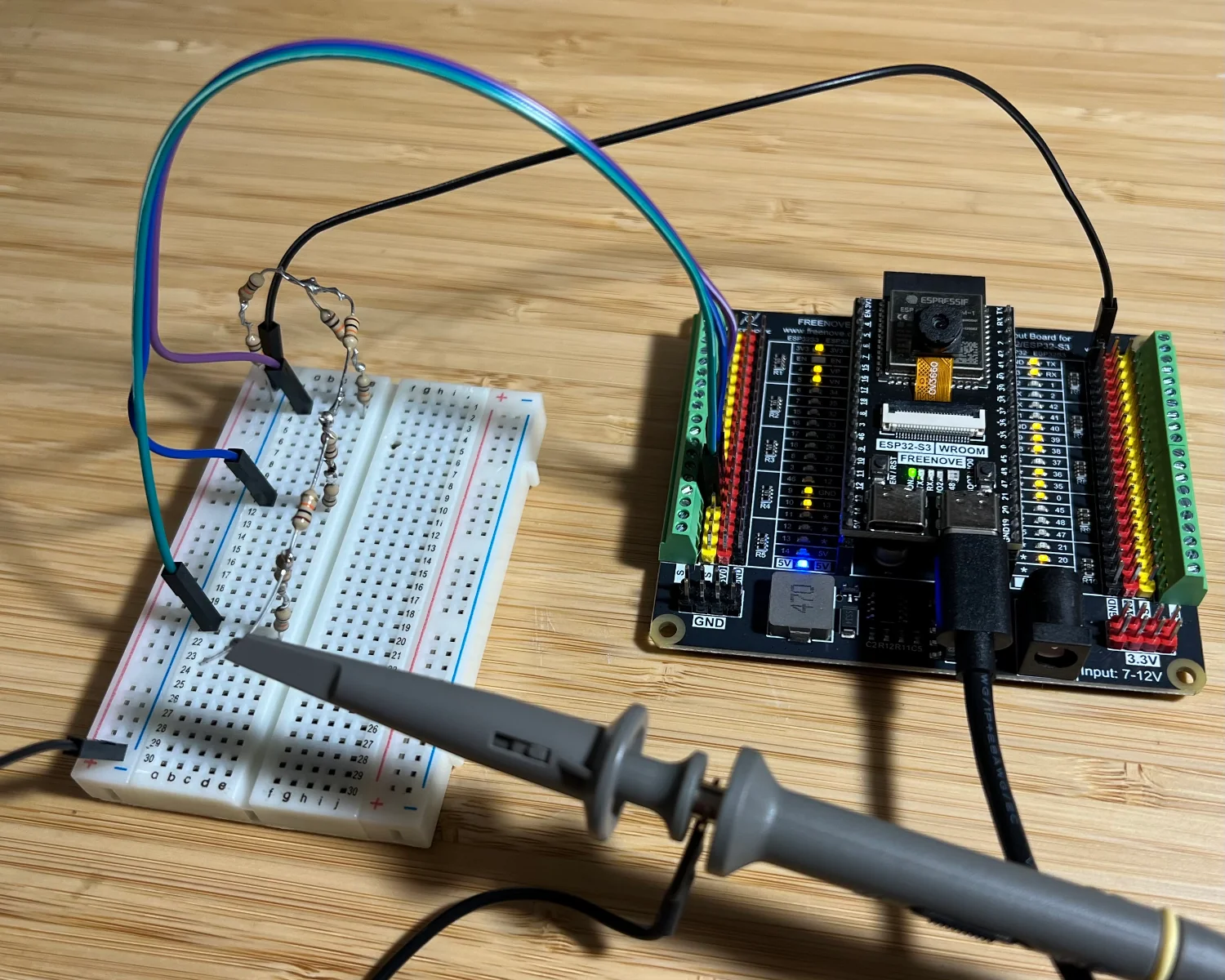
Now we've simulated the circuit and proved our understanding, we can solder up some resistors and build it for real!
To drive the A, B & C pins, we can use a short MicroPython script running on a microcontroller such as an ESP32.
from machine import Pin
from time import sleep_ms

leda = Pin(9, Pin.OUT)
ledb = Pin(10, Pin.OUT)
ledc = Pin(11, Pin.OUT)

curr = 0

while True:
  bits = '{0:03b}'.format(curr)
  leda.on() if bits[2] == '1' else leda.off()
  ledb.on() if bits[1] == '1' else ledb.off()
  ledc.on() if bits[0] == '1' else ledc.off()

  curr = curr + 1
  if curr > 7:
    curr = 0

  sleep_ms(333)
The microcontroller can then be hooked up to the R-2R Ladder DAC, and we can probe the output pin with an oscilloscope.
The oscilloscope's screen reveals the same waveform shape we simulated earlier.
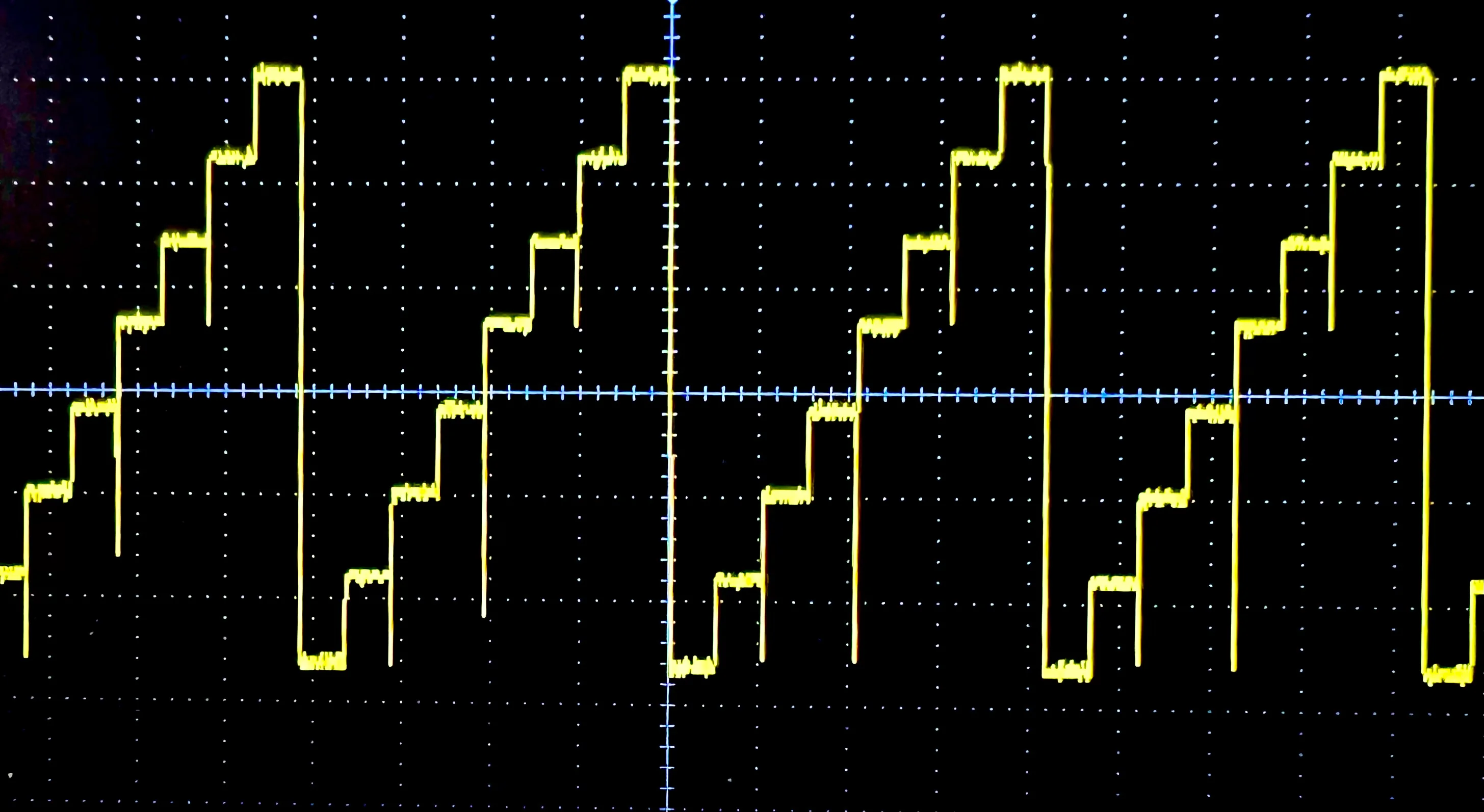
Interestingly, the noise in the physical version goes "down" rather than "up".
This indicates our pins are driven in a different order than the simulation.
Instead of visiting 11 during the transition from 01 to 10, we visit 00 in the real circuit.
All the supporting code and circuit simulations performed above can be found in my back-2-basics repository.
2025-06-09